Cryogenic System and Method of Use

a cryogenic system and cryogenic technology, applied in the field of medical technology, can solve the problems of tissue freezing, inability to operate or withstand pressures greater than 500 psi, use of heat exchangers, etc., and achieve the effects of enhancing nucleation and deposition of saturated gas, enhancing deposition or nucleation modification, and facilitating vacuum

Active Publication Date: 2011-06-23
VARIAN MEDICAL SYSTEMS
View PDF52 Cites 60 Cited by
  • Summary
  • Abstract
  • Description
  • Claims
  • Application Information

AI Technical Summary

Benefits of technology

[0012]In one embodiment, a dual insulative barrier is capable of being formed. The device creates a temperature initiated transient vacuum insulation along the length of a catheter. The device further couples the temperature initiated vacuum with that of a surface modification along the inner tubes / lines to enhance nucleation and deposition of the saturated gas on the outer surface of the inner tubes to create an additional layer of insulation. The enhanced deposition or nucleation modification contributes by making the vacuum more effective. In addition, the saturated gas filled lumen of the outer tube at ambient temperature may be run at any given pressure. For exemplary purposes and not limitation, one embodiment maintains the pressure at atmospheric levels or may control the pressure to elevated or reduced levels.

Problems solved by technology

At present, current systems utilizing liquid nitrogen operate at pressures between 14-480 psi; the systems in use cannot operate or withstand pressures greater that 500 psi.
Further, the use of heat exchangers have been limited to coils placed into a bath of cryogen to allow for time consuming, inefficient passive subcooling of the cryogen in which activation of these devices circulate a cryogen (such as liquid nitrogen) to a probe to create a heat sink, thus resulting in tissue freezing.

Method used


Image

  • Cryogenic System and Method of Use
  • Cryogenic System and Method of Use
  • Cryogenic System and Method of Use

Examples


Embodiment Construction

[0025]In the following detailed description, for purposes of explanation and not limitation, exemplary embodiments disclosing specific details are set forth in order to provide a thorough understanding of the present invention. However, it will be apparent to one having ordinary skill in the art that the present invention may be practiced in other embodiments that depart from the specific details disclosed herein. In other instances, detailed descriptions of well-known devices and methods may be omitted so as not to obscure the description of the present invention.

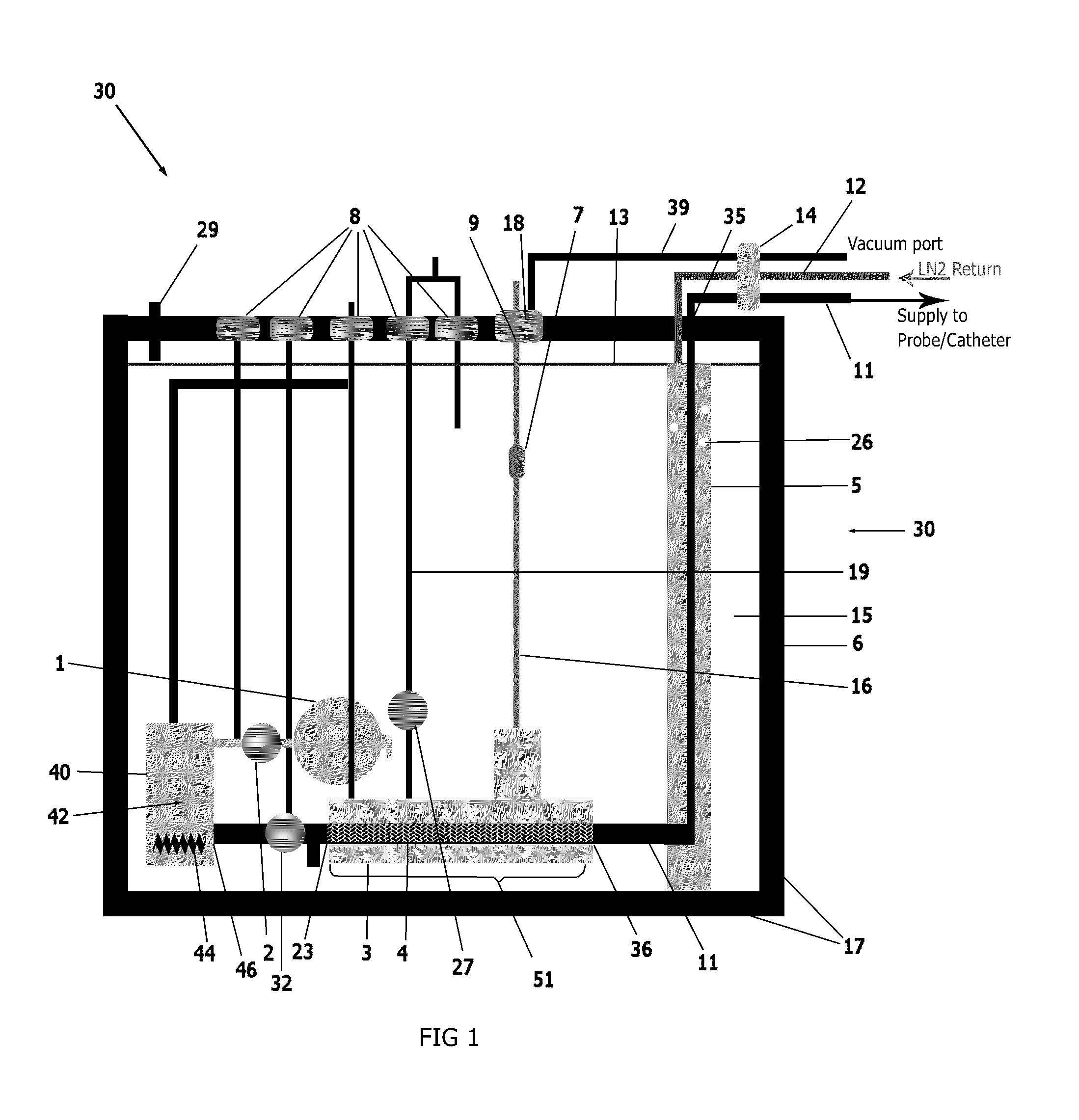
[0026]An external view of a device and system in accordance with one embodiment of the present invention is shown in FIG. 1. The cryogenic system or device 30 has sidewalls 17 which form a container 6 that encloses an internal cavity, or lumen 15. In an embodiment of FIG. 1, the container 6 takes the form of a vacuum insulated dewar 6. The dewar 6 stores liquid cryogen and interconnects a supply line 11 and return line 12 ...


PUM


Abstract

A cryogenic medical device for delivery of subcooled liquid cryogen to various configurations of cryoprobes is designed for the treatment of damaged, diseased, cancerous or other unwanted tissues. The device is a closed or semi-closed system in which the liquid cryogen is contained in both the supply and return stages. The device is capable of generating cryogen to a supercritical state and may be utilized in any rapid cooling systems. As designed, the device comprises a number of parts including a vacuum insulated outer dewar, submersible cryogen pump, baffled linear heat exchanger, multiple pressurization cartridges, a return chamber, and a series of valves to control the flow of the liquid cryogen interconnected with cryotreatment devices including cryoprobes and catheters. The cryogenic medical device promotes subcooling to the tips of various external cryogenic instrument configurations.

Description

RELATED APPLICATIONS[0001]The present application claims priority to U.S. Non-provisional Patent Application No. 12 / 553,005 filed on Sep. 2,2009, which claims priority to U.S. Provisional Patent Application Ser. No. 61 / 093,916 filed on Sep. 3,2008, and titled Modular Pulsed Pressure Device for the Transport of Liquid Cryogen to a Cryoprobe, which is incorporated herein by reference; further claiming priority to U.S. Non-provisional Patent Application Ser. No. 12 / 562,301 filed on Sep. 18, 2009, which claims priority to U.S. Provisional Patent Application Ser. No. 61 / 098,244 filed on Sep. 19, 2008, and titled Nucleation Enhanced Surface Modification to Support Physical Vapor Deposition to Create a Vacuum, which is incorporated herein by reference; further claiming priority to U.S. Non-provisional Patent Application Ser. No. 12 / 607,721 filed on Oct. 28, 2009, and titled A Resorbable Probe Including a Device and Method for Minimally Invasive Tissue Sensitization and Treatment, which is ...

Claims


Application Information

Patent Timeline
Patent Type & Authority Applications(United States)
IPC IPC(8): A61B18/02
CPCA61B18/02A61B2018/0022A61B2018/0212A61B2018/0268A61B18/0218F17C9/00
Inventor BAUST, JOHN M.HAUST, JOHN G.CHEAKS, ROYROBILOTTO, ANTHONY T.SNYDER, KRISTI
Owner VARIAN MEDICAL SYSTEMS
Why Eureka
Try Eureka