Eureka AIR delivers breakthrough ideas for toughest innovation challenges, trusted by R&D personnel around the world.

Electrical anomaly detection method and system

a technology of anomaly detection and detection method, applied in the direction of digital computer details, instruments, nuclear elements, etc., can solve the problems of reducing the quality of electrical signals, difficult management of electrical networks used in large-scale industrial applications, and unusable parts of electrical networks

Inactive Publication Date: 2011-06-23
CORP NUVOLT INC
View PDF27 Cites 91 Cited by
  • Summary
  • Abstract
  • Description
  • Claims
  • Application Information

AI Technical Summary

Benefits of technology

[0034]In one embodiment, the anomaly is an erroneous installation of the sensor, the at least one sensor is a current sensor having at least two conductor holes, and the at least one measured value is a measured voltage value for each of the at least two conductor holes of the sensor, the identification of the required input is a value for a voltage, the threshold reference value is a threshold voltage value, the formula is subtracting the value for the voltage by the threshold voltage value; wherein the anomaly detector applies the formula to each the measured voltage value; if the measure...

Problems solved by technology

Electrical networks used in a large scale industrial application tend to be difficult to manage, for example, because of the number of electrical elements, their complexity in terms of electrical connections, the efficiency of the network planning, the lifetime of the network, etc.
Inappropriate management, replacement or planning of electrical equipments in a large scale industrial application may affect the electrical network and render the electrical equipment or a part of the electrical network unusable, and thus decrease the electrical signal quality.
In animal livestock facilities, the electrical networks are placed in a very demanding environment of high humidity, ammonia gas, frequent spraying of water and electrical equipment operating at many different frequencies.
However, this is not currently achieved.

Method used


Image

  • Electrical anomaly detection method and system
  • Electrical anomaly detection method and system
  • Electrical anomaly detection method and system

Examples


example

[0390]Anomaly: The conductor temperature is over 50° C. This situation is related to an electrical arc and it reduces the equipment lifetime by 70%.

Proposed course of action: To resolve this issue: the electrical arc is located between the circuit breaker and the switch. This could be generated by a loose conductor at a terminal, a bad junction, a burned contact on a motor starter. Inspect all cable junctions, terminals and switches.

[0391]The following is a table listing the events sent by the sensors 14, 15 to the control unit 11 or the algorithm executed by the PC to identify the defect condition. The table also provides the conditions to send the error message to the user.

[0392]Table for the third sequence of events:

StateTransitionDiagnosis#SourceEvent / Data(T0)(T1)Condition1Sensor{e}HighTemp012Sensor{e}VeryHighTemp003Sensor{v}CapTemp4Gateway{v}Temp5ControlConTemp = CapTempunit{c}6Controlunit{m}

[0393]The following is a template for a third type of message to be displayed to the us...


PUM


Abstract

There are provided a method and a system for real time monitoring of a powered on electrical network in a facility in order to detect an electrical anomaly while the electrical network is in use. The system comprises a sensor data receiver for receiving real time sensor data including at least one measured value measured in real time by at least one sensor installed on a conductor of the electrical network in the facility while the electrical network is in use; an anomaly detector for retrieving an anomaly detection rule from an anomaly detection rule database, the rule having an identification of a required input, a formula, and a threshold reference value, for a detection of an anomaly; receiving the real time sensor data from the sensor data receiver and extracting at least one relevant measured value from the at least one measured value using the identification of the required input; comparing the at least one relevant measured value to the threshold reference value according to the formula to determine one of a presence and an absence of the anomaly in the real time sensor data; an event generator controlled by the processor for retrieving and providing anomaly monitoring data if the anomaly is determined to be present by the processor, the anomaly monitoring data including an indication of a monitoring course of action to be carried out to address the anomaly determined to be present.

Description

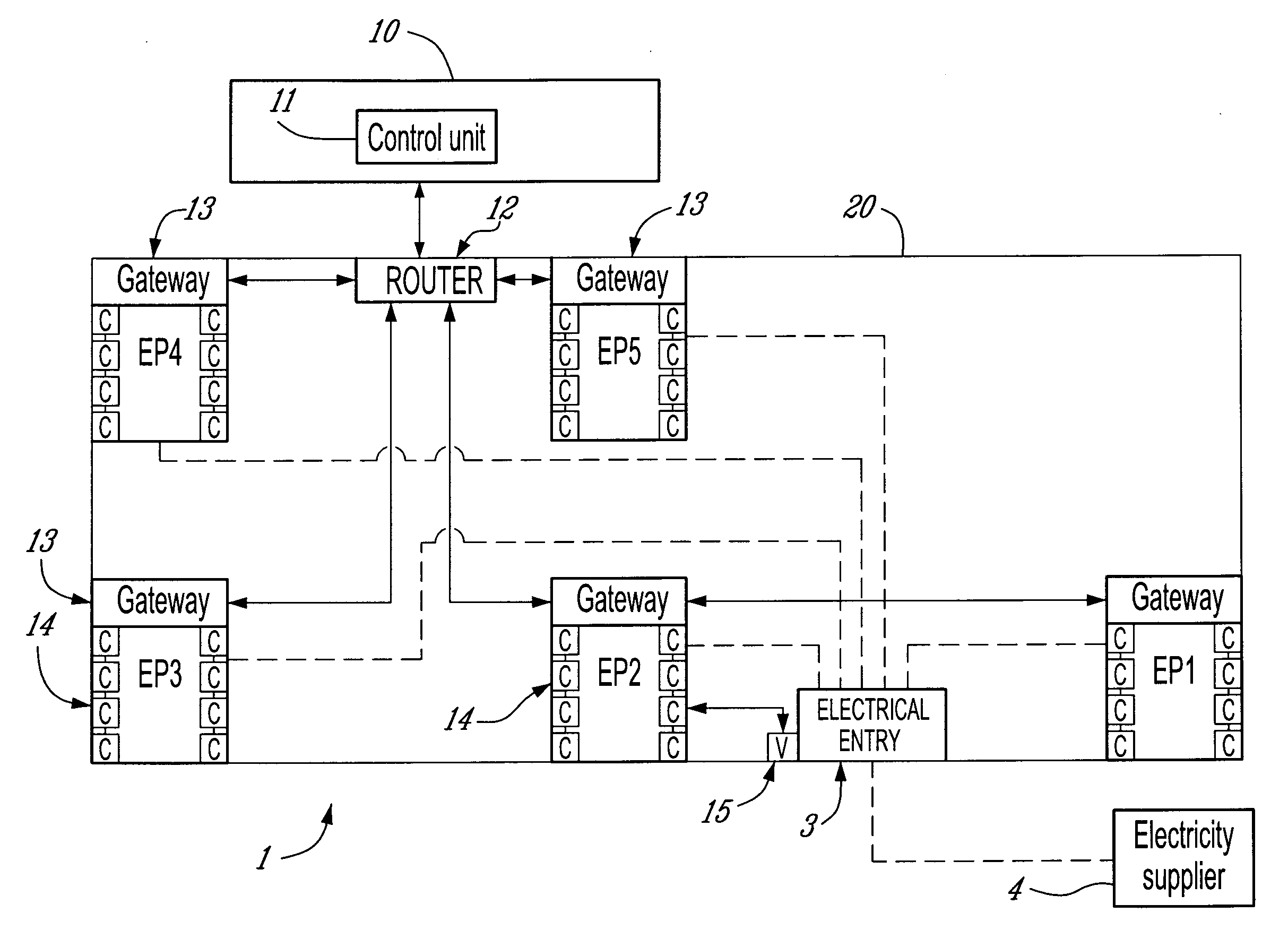
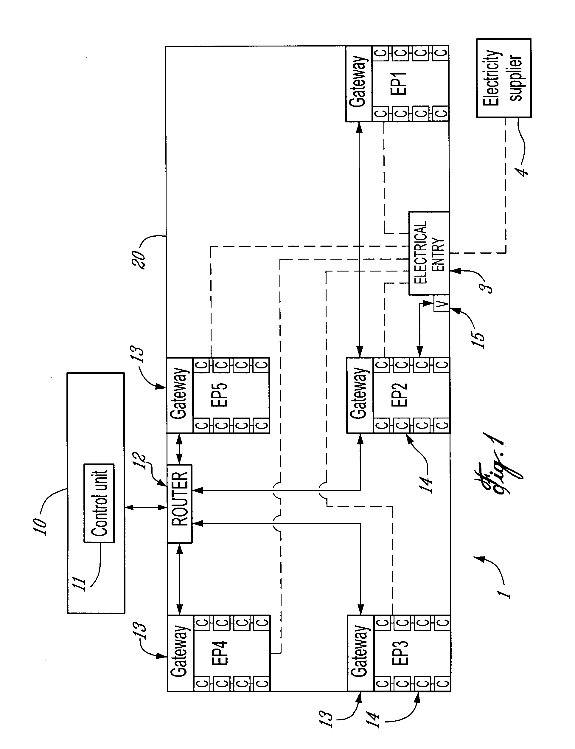
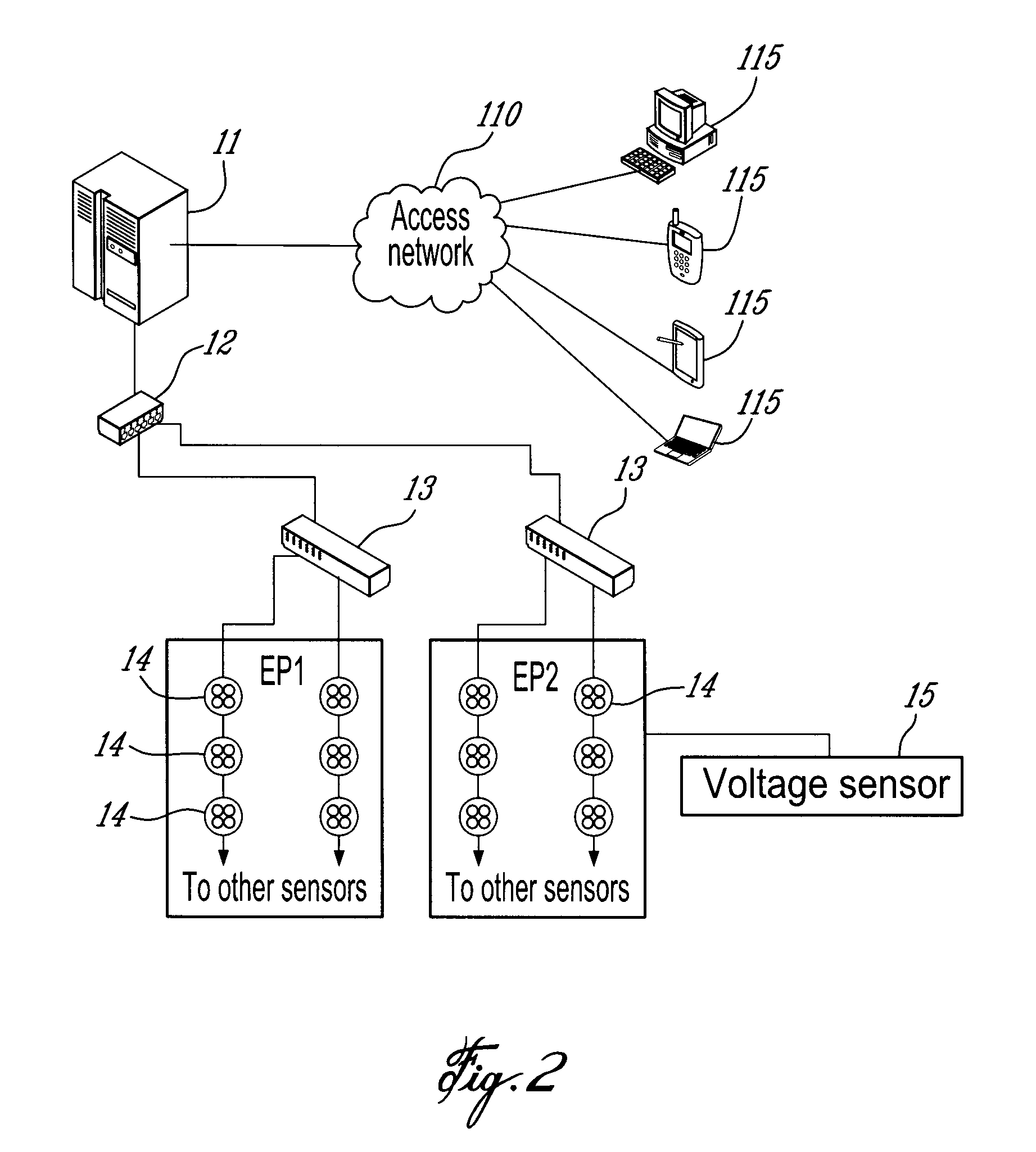
CROSS-REFERENCE TO RELATED APPLICATIONS[0001]This application claims priority of U.S. provisional patent application No. 61 / 044,631 filed on Apr. 14, 2008 by Applicant.TECHNICAL FIELD[0002]This invention relates to electrical anomaly detection in electrical distribution and grounding networks and more particularly, to detecting an anomaly and providing course of action data.BACKGROUND OF THE ART[0003]Electrical networks are used in industrial applications such as, for example, in production, manufacturing, industrial or agricultural facilities. These networks, when implemented in large scale facilities, may comprise various electrical equipments such as motors, pumps, heaters, and cooling systems to accomplish various industrial tasks. Electrical networks used in a large scale industrial application tend to be difficult to manage, for example, because of the number of electrical elements, their complexity in terms of electrical connections, the efficiency of the network planning, th...

Claims


Application Information

Patent Timeline
IPC IPC(8): G06F19/00
CPCG01R19/2513G01R31/025H02H3/00G01R31/343G01R31/088G01R31/52
Inventor MONTREUIL, MICHELFECTEAU, KARL
Owner CORP NUVOLT INC
Why Eureka
Eureka Blog
Learn More