Plant for Assembling Mechanical Parts on Bodies of Motor-Vehicles

a technology for motor vehicles and parts, which is applied in the direction of manufacturing tools, metal working apparatuses, transportation and packaging, etc., can solve the problems of complex logistic management of the plant, no operation useful within the assembly cycle, and the type occupies a relatively large space in the assembly plant, so as to achieve a high degree of operative flexibility

Active Publication Date: 2011-06-30
COMAU SPA
View PDF17 Cites 23 Cited by
  • Summary
  • Abstract
  • Description
  • Claims
  • Application Information

AI Technical Summary

Benefits of technology

[0015]Due to the abovementioned characteristics, the plant according to the invention has a high degree of operative flexibility, given that it is adaptable to operate on different types of motor-vehicles (for example both on cars and on vans or light tracks) and / or on different models of motor-vehicles (for example different car models) and / or on different versions of the same model (for example on the sedan version, on the station-wagon version and on the cabriolet version). At the same time, the provision of the abovementioned sub-pallets allows pre-mounting thereon, off-line, the mechanical parts and then mounting said parts on the pallet along the line, through a single and quick operation.

Problems solved by technology

The plants of this type have the drawback of occupying a relatively extensive space within the assembly plant.
A further drawback lies in the fact that the abovementioned connection transverse sections, though occupying useful space in the plant, are entirely passive, in the sense that no operation useful within the assembly cycle is carried out there along.
A further serious drawback lies in the fact that access to the useful sections of the line from the side facing inwards the endless path is difficult, hence the logistic management of the plant is complicated, especially regarding supplying parts to the various stations of the line.

Method used


Image

  • Plant for Assembling Mechanical Parts on Bodies of Motor-Vehicles
  • Plant for Assembling Mechanical Parts on Bodies of Motor-Vehicles
  • Plant for Assembling Mechanical Parts on Bodies of Motor-Vehicles

Examples


Embodiment Construction

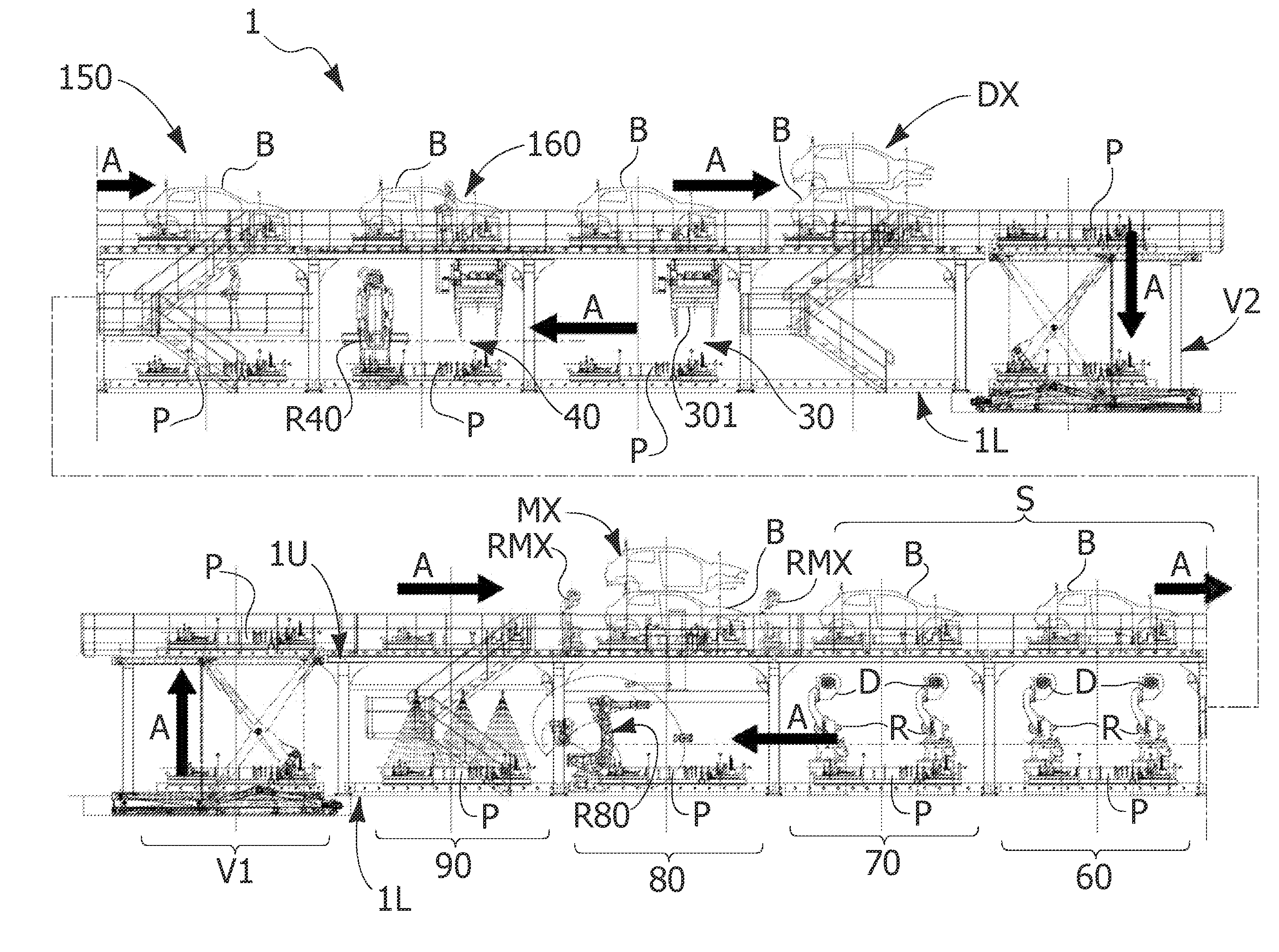
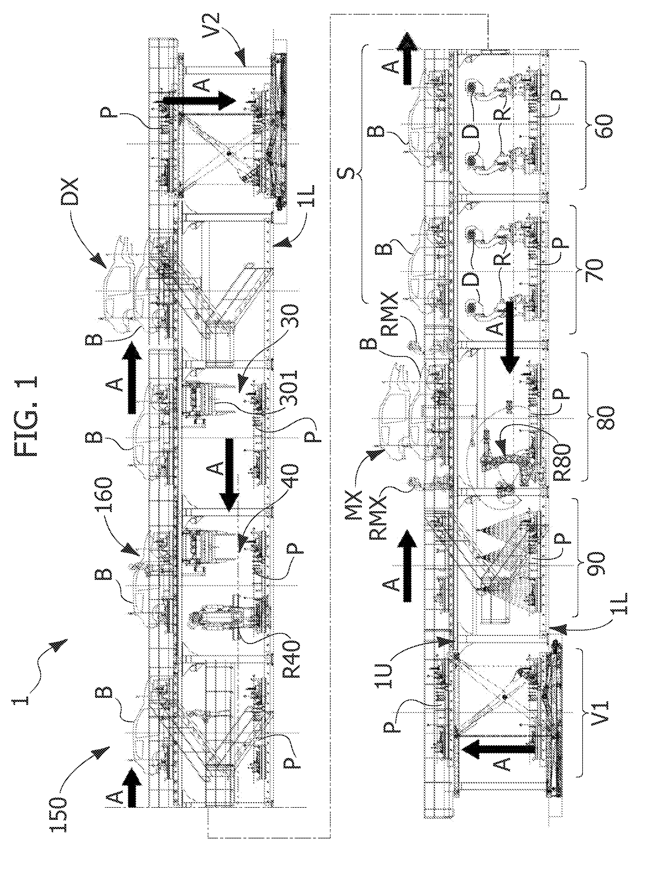
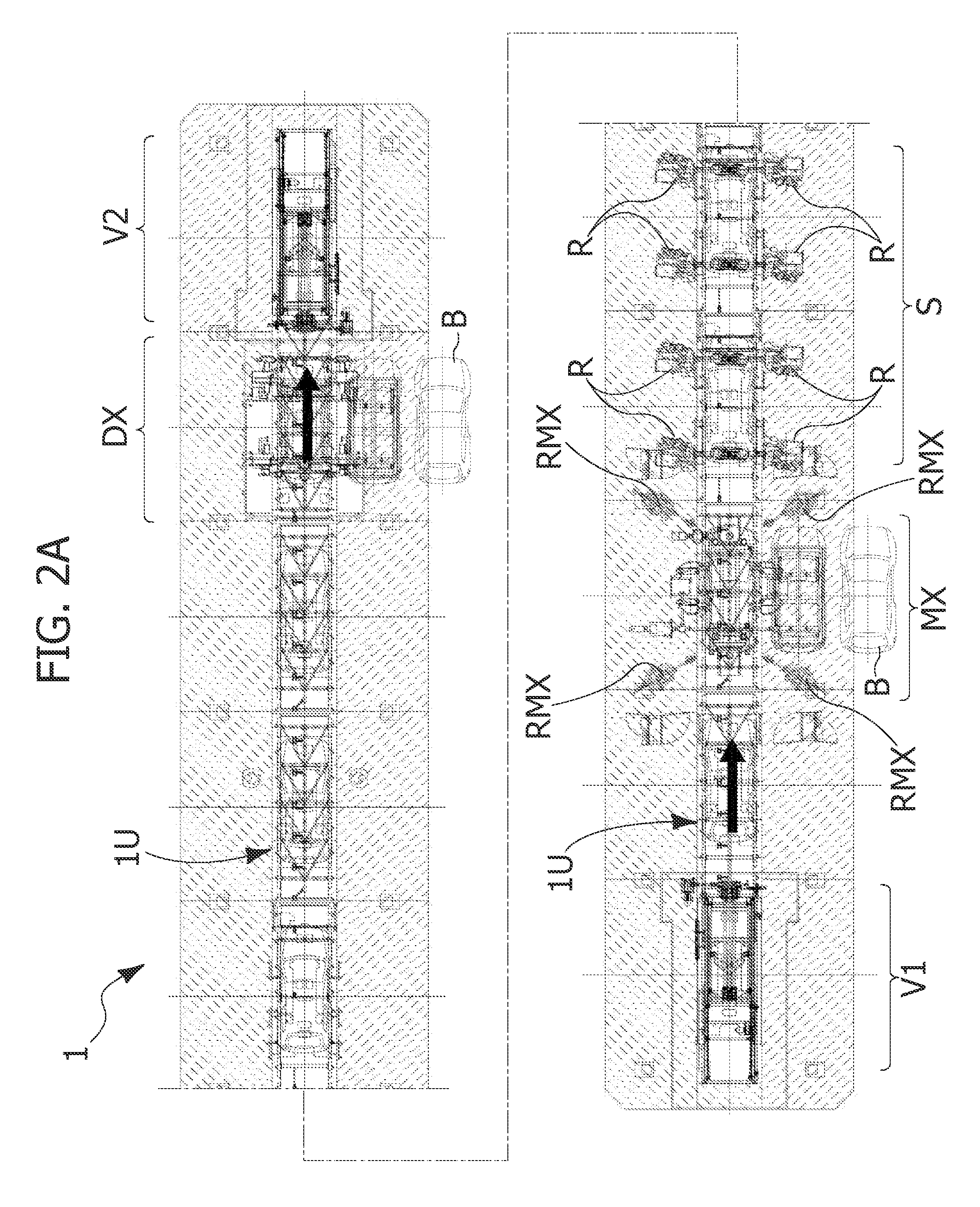
[0034]In FIGS. 1 and 2, a plant for assembling motor-vehicles is indicated in its entirety with reference number 1. The plant 1 comprises a conveying line which follows an endless path in a vertical plane, with a lower section, indicated in its entirety with reference number 1L, along which pallets P are conveyed in succession in a first direction (from right to left with reference to the drawings) and an upper section, indicated in its entirety with 1U superimposed at a suitable distance on the lower section 1L and aligned in the same direction. Along the upper section 1U, the pallets P move in a direction opposite to the direction of movement of the pallets along the lower section 1L (i.e. from left to right with reference to the drawings). The direction of the movement of the pallets in the plant 1 is indicated by the arrows A in FIG. 1.

[0035]A vertical transfer station V1 with a lifting device which lifts a respective pallet P from the lower section 1L to the upper section 1U is...


PUM

PropertyMeasurementUnit
movementaaaaaaaaaa
flexibilityaaaaaaaaaa
timeaaaaaaaaaa

Abstract

A plant for assembling mechanical parts on bodies of motor-vehicles comprises an endless conveying line and a plurality of pallets movable along the conveying line, each receiving mechanical parts of the motor-vehicle along a first section of the line. Means for loading a respective motor-vehicle body on a respective pallet at a loading station, located at the beginning of a second section of the conveying line, downstream of the abovementioned first section with reference direction of movement of the pallets are provided. At least one bolting station for bolting the mechanical parts on the respective body along the abovementioned second section is provided. The abovementioned second section of the line is superimposed to the first section and aligned therewith, so that the pallets move along a closed loop in a vertical plane, moving along the upper section in a direction opposite to their direction of movement along the lower section.

Description

FIELD OF THE INVENTION[0001]The present invention relates to relates to a plant for assembling mechanical parts on bodies of motor-vehicles.BACKGROUND[0002]Plants are known (see for example document GB 2 136 330) comprising:[0003]an endless conveying line,[0004]a plurality of pallets movable along the conveying line, each receiving a number of mechanical parts of the motor-vehicle along a first section of the conveying line,[0005]means for loading a respective motor-vehicle body on a respective pallet at a loading station, located at the beginning of a second section of the conveying line, downstream of said first section with reference to the direction of movement of the pallets,[0006]at least one bolting station arranged in said second section of the conveying line and provided with means for bolting said mechanical parts to said body, and[0007]means for unloading the respective body with the mechanical parts bolted thereon at the end of said second section of the conveying line.[...

Claims


Application Information

Patent Timeline
Patent Type & Authority Applications(United States)
IPC IPC(8): B23P19/06
CPCB23P19/06B23P2700/50Y10T29/53417B62D65/18B62D65/12B62D65/02
Inventor CARDANI, SERGIORUMIANO, GUIDOPUTIRI, ANGELO
Owner COMAU SPA
Why Eureka
Try Eureka