
Cng time fill system and method with safe fill technology

a filling system and filling technology, applied in the field of compressed natural gas (cng) compressors, can solve problems such as the shutting down of the compression system

Active Publication Date: 2011-06-30
CLEAN ENERGY FUELS CORP
View PDF34 Cites 15 Cited by
  • Summary
  • Abstract
  • Description
  • Claims
  • Application Information

AI Technical Summary

Benefits of technology

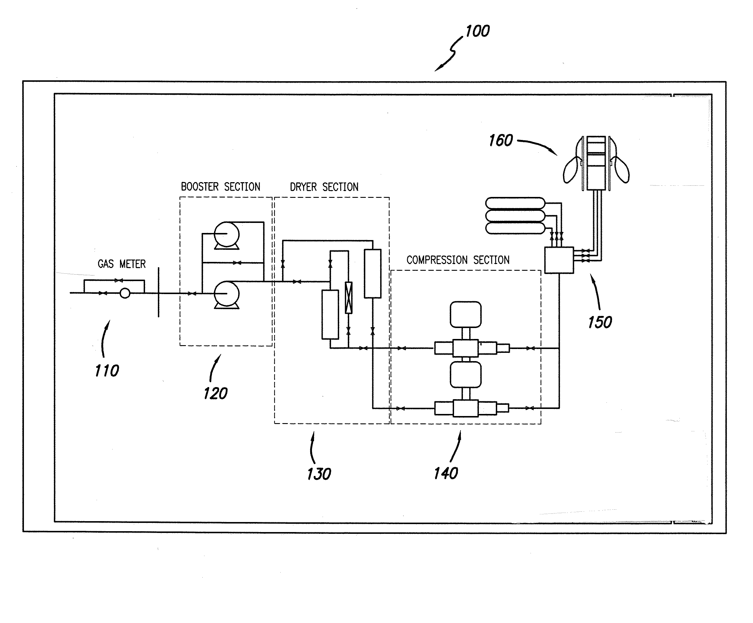
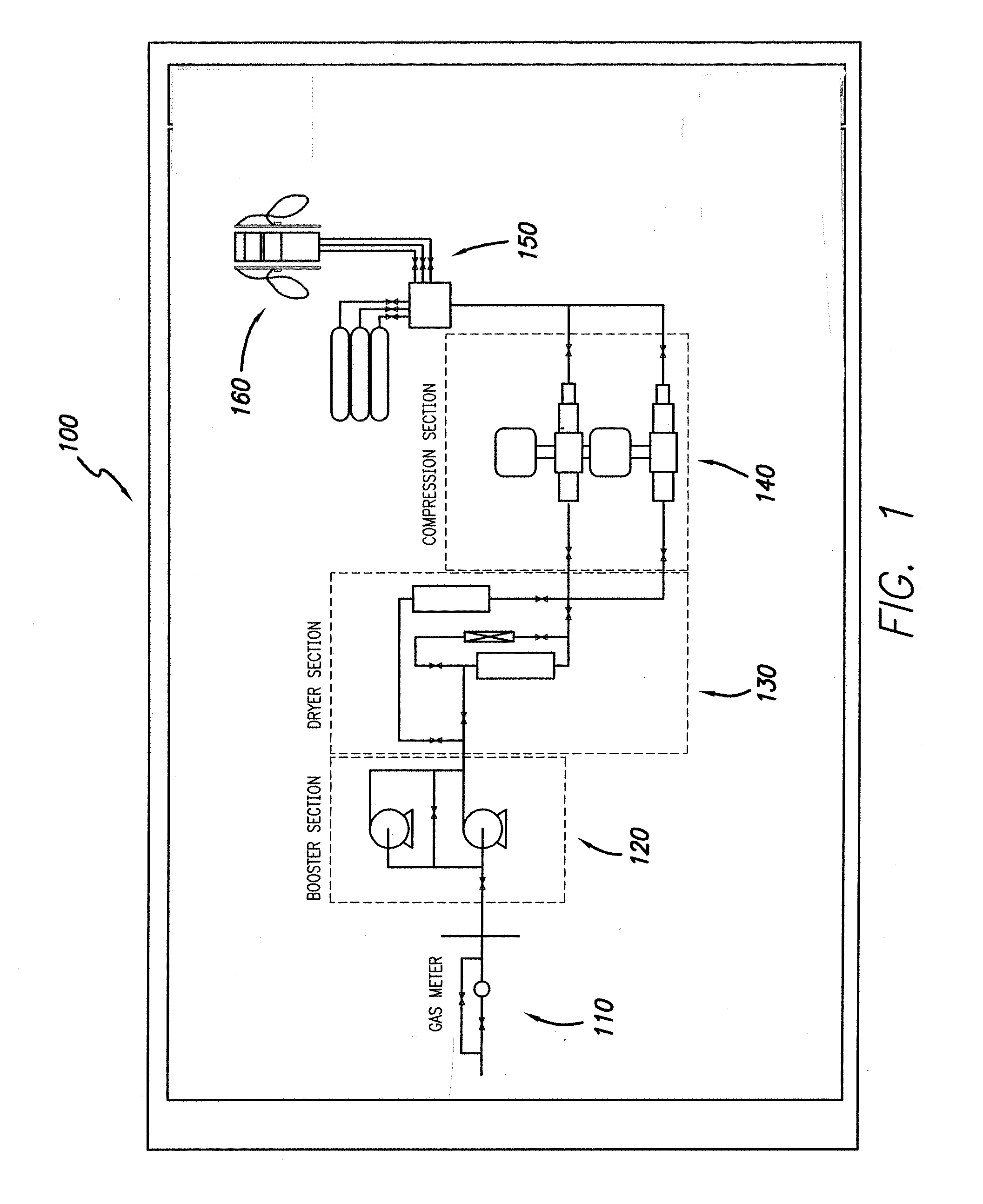
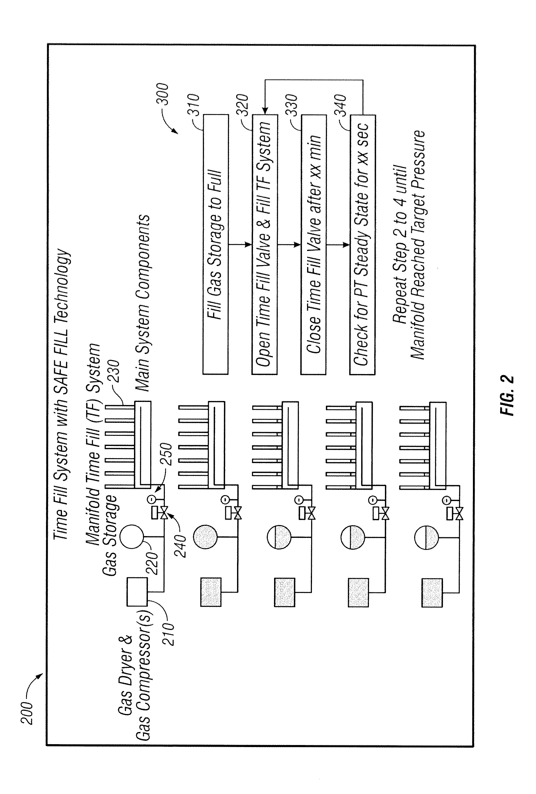
[0003]The present invention provides a time fill CNG refueling station with safe fill technology. In particular, the invention provides a design and method for measuring and checking for steady static pressure on a time fill manifold system periodically throughout the filling process, thus providing the ability to incorporate safety measures to protect against gas leaks due to broken fittings, hoses or vehicles having onboard gas leaks.

Problems solved by technology

However, if the manifold time fill system fails to achieve a steady static pressure within a predetermined time, the compression system is shut down and a system operator is warned of a potential leak.

Method used


Image

  • Cng time fill system and method with safe fill technology
  • Cng time fill system and method with safe fill technology
  • Cng time fill system and method with safe fill technology

Examples


Embodiment Construction

[0015]In the following paragraphs, the present invention will be described in detail by way of example with reference to the attached drawings. Throughout this description, the preferred embodiment and examples shown should be considered as exemplars, rather than as limitations on the present invention. As used herein, the “present invention” refers to any one of the embodiments of the invention described herein, and any equivalents. Furthermore, reference to various feature(s) of the “present invention” throughout this document does not mean that all claimed embodiments or methods must include the referenced feature(s).

[0016]The present invention is directed to a CNG time fill system with safe fill technology design. Specifically, some embodiments provide a design and method for periodically measuring and checking for steady static pressure on a time fill manifold system throughout the filling process. This provides the ability to incorporate safety measures to protect against gas ...


PUM


Abstract

The present invention provides a CNG time fill system, comprising a compression system including a gas dryer and one or more gas compressors, a gas storage system for storing the natural gas, a manifold time fill system for filling a plurality of natural gas vehicles with the natural gas, a pressure transducer or pressure transmitter for detecting the pressure within the manifold time fill system, and an automatic shut off valve for selectively stopping the flow of gas into the manifold time fill system.

Description

FIELD OF THE INVENTION[0001]The present invention relates generally to compressors for compressed natural gas (CNG) stations for refueling motor vehicles, and more particularly to a CNG time fill system and method with safe fill technology.BACKGROUND OF THE INVENTION[0002]Most time fill CNG stations are designed to fill multiple natural gas vehicles (NGVs) through a series of CNG hoses connected to a manifold system. A typical compression system (e.g., including gas dryer, gas compressor, gas storage and valve panel) will deliver CNG to the entire manifold including the NGVs connected to the manifold. The compression system will continue to charge the manifold until it reached a calculated target pressure. Due to different configurations (e.g., timing of individual vehicle connections and starting pressure of each vehicle), it is difficult to incorporate safety measures against gas leaks caused by broken fittings, hoses or vehicles with onboard gas leaks.SUMMARY OF THE INVENTION[000...

Claims


Application Information

Patent Timeline
IPC IPC(8): B65B31/02
CPCF17C5/007F17C5/06F17C2205/0326F17C2221/033F17C2223/0123F17C2227/0157F17C2270/0139F17C2250/043F17C2250/0473F17C2250/0626F17C2250/0636F17C2260/038F17C2265/065F17C2227/0185
Inventor DING, DENIS
Owner CLEAN ENERGY FUELS CORP
Learn More