Vehicle drive motor

a technology of drive motor and stator coil, which is applied in the direction of dynamo-electric machines, electrical apparatus, magnetic circuit shapes/forms/construction, etc., can solve the problems of increasing the size of the motor casing, reducing the size, and not developing a structure to alleviate the heat emission of the stator coil while avoiding an increase in size, so as to achieve the cooling effect of the stator coil yet further efficiently

Inactive Publication Date: 2011-06-30
NTN CORP
View PDF3 Cites 7 Cited by
  • Summary
  • Abstract
  • Description
  • Claims
  • Application Information

AI Technical Summary

Benefits of technology

[0023]As described above, where the entire stator, excluding the inner periphery of the individual core portions, is covered by the stator covering and an oil cooling structure is

Problems solved by technology

While it is very important in the vehicle drive motor to alleviate heat emission occurring in a stator coil as a result of the flow of a large electric current therethrough, no structure for alleviating heat emission in the stator coil while avoiding an increase in size has yet been developed.
Also, while in the vehicle dri

Method used


Image

  • Vehicle drive motor
  • Vehicle drive motor
  • Vehicle drive motor

Examples


second embodiment

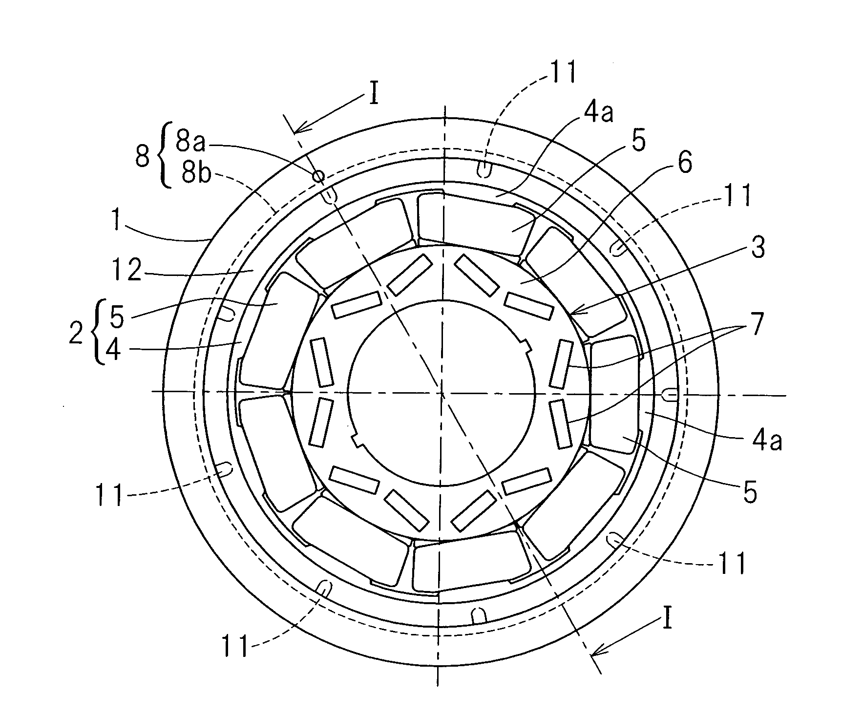
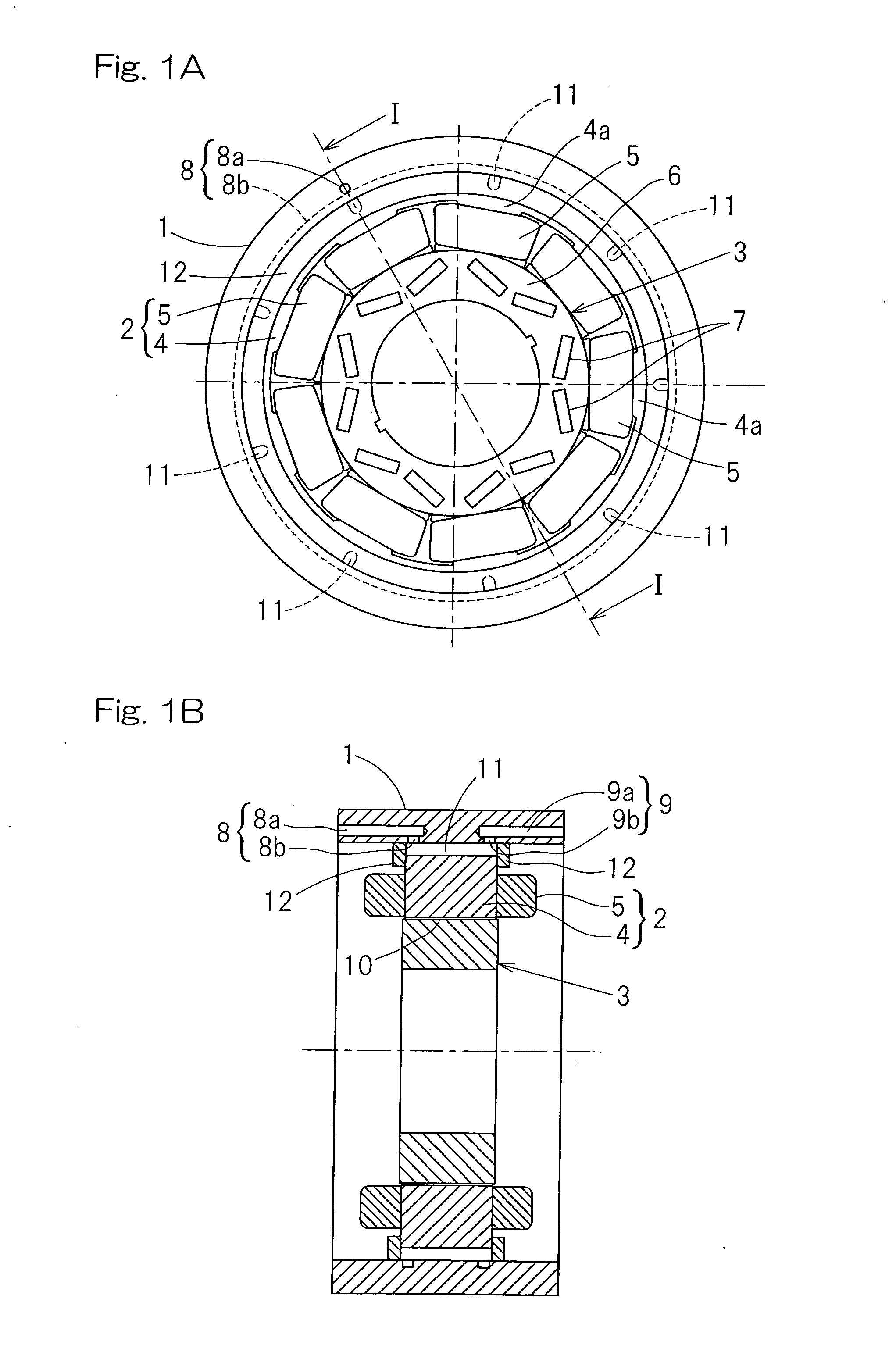
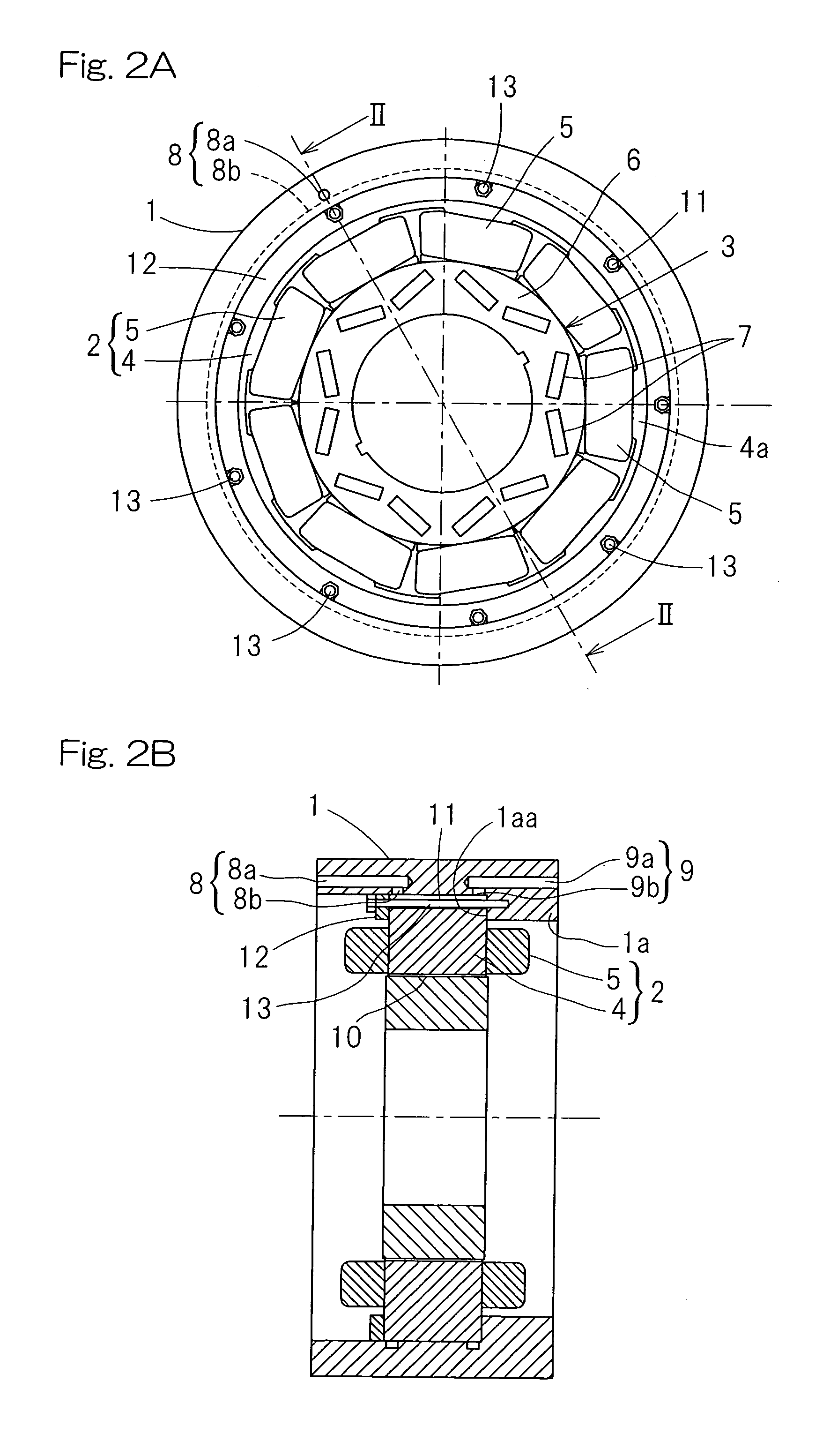
[0046]In the case of the second embodiment, in order to fix the stator core 4 to the inner periphery of the motor casing 1, the stator core grooves 11 are used as insertion holes for receiving the respective bolts 13 without employing any complicated structure in one or both of the motor casing 1 and the stator core 4, thereby facilitating the fixing of the stator core 4 to the inner periphery of the motor casing 1.

[0047]FIGS. 3A and 3B illustrate a third embodiment of the present invention. FIG. 3A is a front elevational view showing the vehicle drive motor according to the third embodiment and FIG. 3B is a cross sectional view taken along the line III-III in FIG. 3A. The vehicle drive motor shown therein is similar to that according to the first embodiment shown in and described with particular reference to FIGS. 1A and 1B, but differs therefrom in that the ring shaped lid members 12 for closing the respective opposite ends of each of the stator core grooves 11 are provided with r...

third embodiment

[0048]In the case of this third embodiment, a portion of the lubricant oil supplied from the oil supply passage 8 towards the stator core grooves 11 can be injected onto the stator coil 5, which forms a source of heat emission, from the holes 14 (or the grooves) in the lid members 12, and, therefore, the stator coil 5 can be cooled directly, resulting in a further increase of the cooling efficiency of the stator 2.

[0049]FIGS. 4A and 4B illustrate a fourth embodiment of the present invention. FIG. 4A is a front elevational view showing the vehicle drive motor according to the fourth embodiment and FIG. 4B is a cross sectional view taken along the line IV-IV in FIG. 4A. The vehicle drive motor shown therein is similar to that according to the first embodiment shown in and described with particular reference to FIGS. 1A and 1B, but differs therefrom in that each of the ring shaped lid members 12 for closing the respective opposite ends of each of the stator core grooves 11 is of an L-s...

fourth embodiment

[0050]In the case of the fourth embodiment, the lubricant oil supplied under pressure from the outside into the oil supply passage 8 of the motor casing 1 is introduced from the radially extending oil supply passageway 8c of the oil supply passage 8 into the one end side of each of the stator core grooves 11 through a ring shaped internal cavity 15 in the lid member 12 used to close the one end of each of the stator core groove 11. The lubricant oil flowing to the opposite end of each of the stator core grooves 11 is discharged from the radially extending oil discharge passageway 9c of the oil discharge passage 9 through the ring shaped internal cavity 15 in the lid member 12 used to close the opposite end of each of the stator core grooves 11.

[0051]As hereinabove described, in the fourth embodiment, the ring shaped internal cavity 15 in the lid member 12 used to close the one end of each of the stator core grooves 11 defines a path through which the lubricant oil introduced from th...


PUM


Abstract

A vehicle drive motor, capable of efficiently cooling the motor stator without being accompanied by an increase in size, includes a stator having an annular stator core, provided in an inner periphery of a tubular motor casing, and a stator coil provided in the stator core, and a rotor on an inner side of the stator core and rotatable relative to the stator. The motor casing includes an oil supply passage and an oil discharge passage in the motor casing and opening at an inner diametric surface of the motor casing, which are opposite axially to each other. Stator core grooves communicated with the oil supply passage and the oil discharge passage extend axially in an outer diametric surface of the stator core. Accordingly, lubricant oil may flow from the oil supply passage towards the oil discharge passage through the stator core groove.

Description

CROSS REFERENCE TO RELATED APPLICATIONS[0001]This application claims the benefit under 35 U.S.C. Section 371, of PCT International Application No. PCT / JP2009 / 004252, filed Aug. 31, 2009, which claimed priority to Japanese Application No. 2008-225562, filed Sep. 3, 2008, and No. 2009-095424, filed Apr. 10, 2009, in the Japanese Patent Office, the disclosures of which are hereby incorporated by reference.BACKGROUND OF THE INVENTION[0002]1. Field of the Invention[0003]The present invention relates to a vehicle drive motor that may be used as a drive source in various motor driven vehicles such as, for example, automotive vehicle and railroad vehicles.[0004]2. Description of Related Art[0005]The vehicle drive motor, particularly the drive motor used as a drive source in an electric car or a hybrid car is required to have not only a compact and lightweight feature, but also a capability of providing the maximum output for energy saving purpose. Where a high power motor is desired to be d...

Claims


Application Information

Patent Timeline
IPC IPC(8): H02K9/19
CPCH02K9/19H02K1/20
Inventor OKADA, KOICHIOZAKI, TAKAYOSHIMAKINO, YUSUKE
Owner NTN CORP
Why Eureka
Try Eureka