
Electric field driven liquid crystal lens cell and stereoscopic image display device using the same

a liquid crystal lens and electric field technology, applied in the field of display devices, can solve the problems of abnormal 3d display region, liquid crystal movement is excessively sensitive to voltage variation, and the spacer itself cannot function as a lens

Active Publication Date: 2011-06-30
LG DISPLAY CO LTD
View PDF5 Cites 52 Cited by
  • Summary
  • Abstract
  • Description
  • Claims
  • Application Information

AI Technical Summary

Benefits of technology

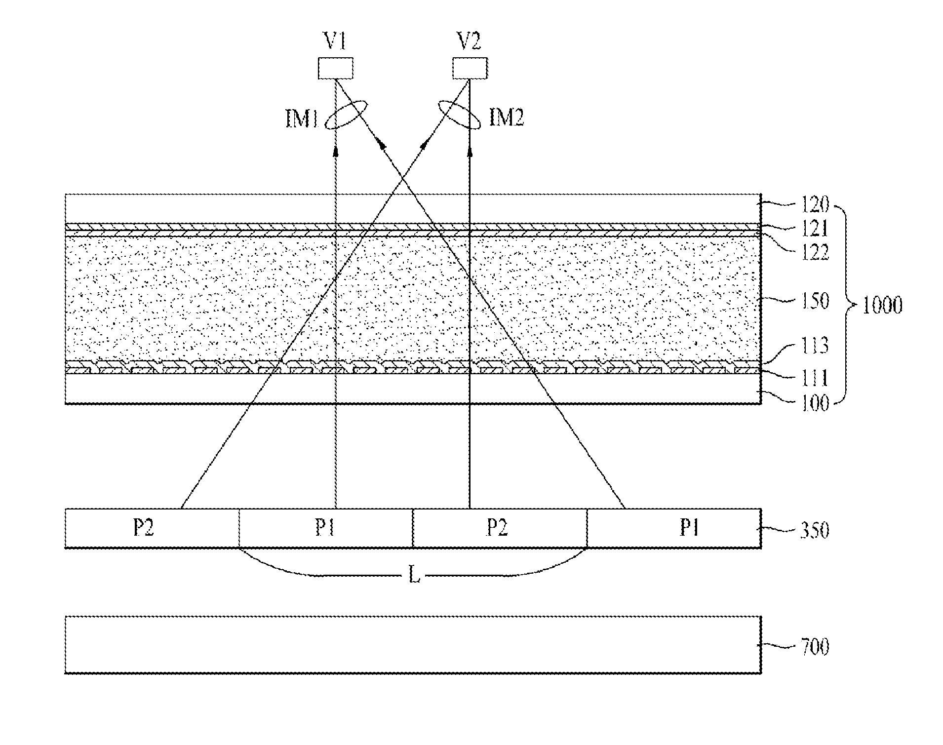
[0025]An object of the present invention is to provide an electric field driven liquid crystal lens in which the position of a spacer is adjustable to prevent a lens surface error, and a stereoscopic display device using the same.

Problems solved by technology

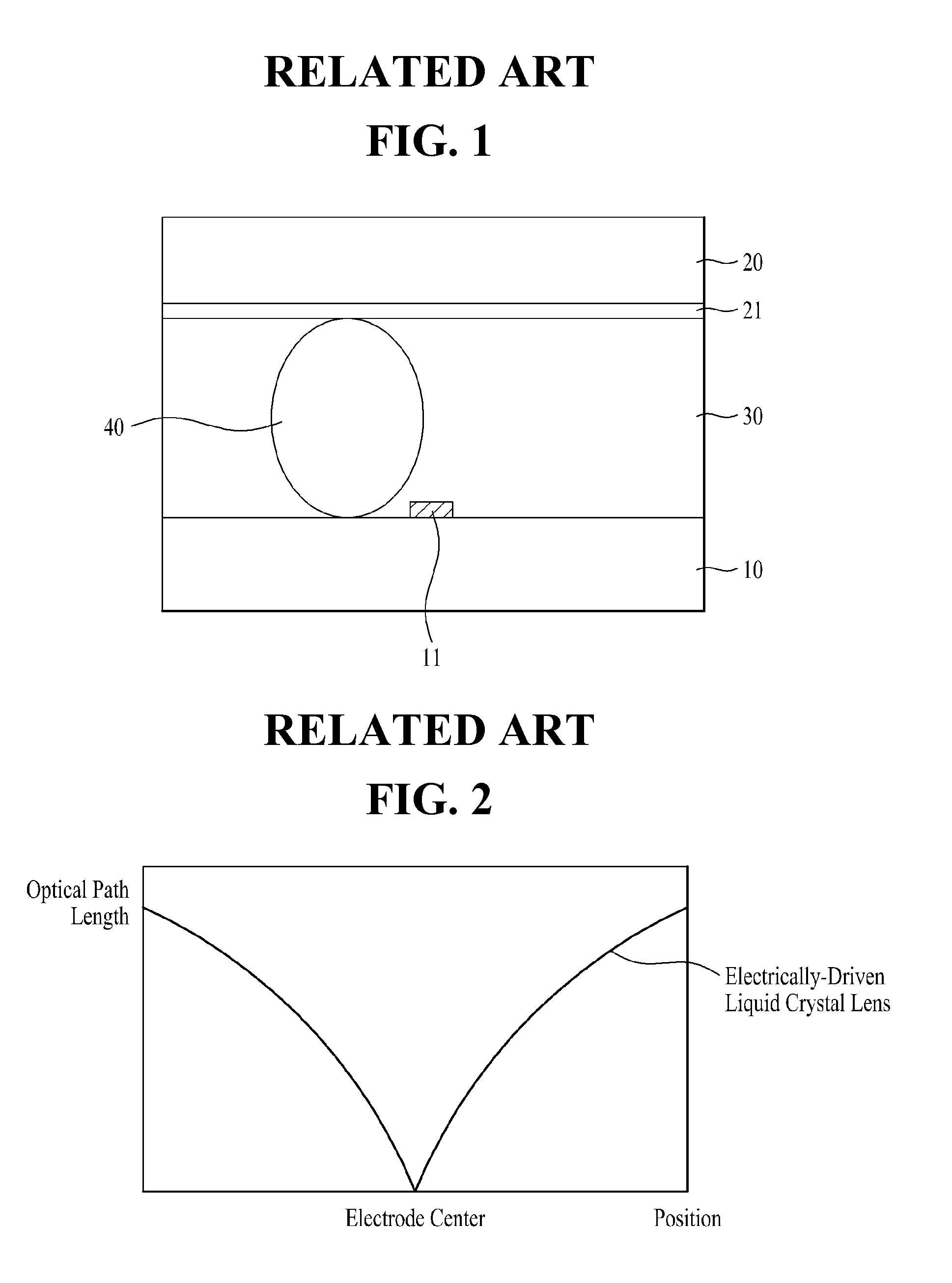
Accordingly, liquid crystals have a slightly distorted distribution rather than a predetermined distribution, whereby a refractive index of light cannot exhibit parabolic spatial distribution, or movement of the liquid crystals is excessively sensitive to voltage variation.
Therefore, a distorted lens surface may be identified with the naked eye, or an abnormal 3D display region may occur.
However, the spacer itself cannot function as a lens.
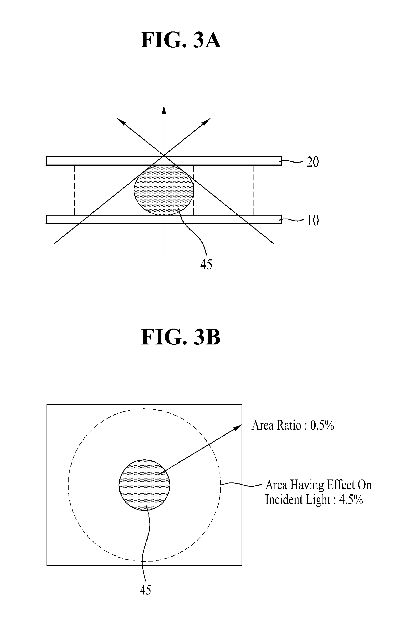
Even a region around the spacer may exhibit distortion in a transmission direction of light, or may intercept light due to the existence of the spacer.
Second, the distortion in the transmission of light occurs in an area equal to approximately 9 times an area of the spacer, rather than occurring only in an area of the spacer and thus, the entire electric field driven liquid crystal lens may exhibit a distinguishable lens error as the distortion occurs due to light transmitted laterally.
Third, the function of the related art electric field driven liquid crystal lens may deteriorate.
If lens error occurs, respective lens regions of the electric field driven liquid crystal lens may have different refractive indices and in turn, such a refractive index difference may cause an irregular lens interface.

Method used


Image

  • Electric field driven liquid crystal lens cell and stereoscopic image display device using the same
  • Electric field driven liquid crystal lens cell and stereoscopic image display device using the same
  • Electric field driven liquid crystal lens cell and stereoscopic image display device using the same

Examples


Embodiment Construction

[0040]Reference will now be made in detail to the embodiments of the present invention, examples of which are illustrated in the accompanying drawings.

[0041]FIG. 4 is a view illustrating incidence angles and refraction angles at different lens surface regions under the assumption of arranging column spacers at “A” and “B” positions.

[0042]As illustrated in FIG. 4, when light emitted from a light source below a lens transmits through a lens surface, straight incident light directly transmits through the lens surface and travels in a straight path, whereas light is incident on the edge of the lens surface by a predetermined inclination angle and thereafter, exits from the lens surface at a predetermined refraction angle. This occurs since the lens surface has a curvature and since it is centrally provided with a column spacer. For example, as illustrated in FIG. 4, if it is assumed that a column spacer is located at the “A” position, light enters the lens surface at an incidence angle ...


PUM

PropertyMeasurementUnit
refraction angleaaaaaaaaaa

Abstract

An electric field driven liquid crystal lens cell including a first substrate and a second substrate arranged opposite each other, a first plurality of split electrodes formed on the first substrate, each of the first plurality of split electrodes corresponding to one of a plurality of lens regions, a second electrode formed over an entire first surface of the second substrate, a voltage source to apply differing voltages to the first and second plurality of split electrodes, a spacer formed between the first substrate and the second substrate, the location of the spacer corresponding to the vertex of the lens when voltages are applied to at least one of the first plurality of split electrodes and the second electrode, and a liquid crystal layer disposed between the first substrate and the second substrate.

Description

[0001]This application claims the benefit of Korean Patent Application No. P2009-0131048 filed on Dec. 24, 2009, which is hereby incorporated by reference.BACKGROUND OF THE INVENTION[0002]1. Field of the Invention[0003]The present invention relates to a display device, and more particularly, to an electric field driven liquid crystal lens in which the position of a spacer is adjustable to prevent a lens surface error, and a stereoscopic display device using the same.[0004]2. Discussion of the Related Art[0005]At present, services for rapid dissemination of information, based on the construction high-speed information communication networks, have developed from a simple “listening and speaking” service, such as current telephones, to a “watching and listening” multimedia type service based on digital terminals used for high-speed processing of characters, voices, and images. Ultimately, such services are expected to be developed into hyperspace 3-dimensional (3D) stereoscopic informa...

Claims


Application Information

Patent Timeline
Patent Type & Authority Applications(United States)
IPC IPC(8): G02F1/1335G02B30/25G02B30/28
CPCG02B3/08G02B3/12G02B27/2214G02B27/225H04N13/0452G02F1/29G02F2001/294G02F2203/28H04N13/0404G02F1/13394H04N13/305H04N13/356G02F1/294G02B30/28G02F1/1335G02B30/27
Inventor LEE, BYUNG-JOOKIM, SUNG-WOO
Owner LG DISPLAY CO LTD
Learn More