Perpendicular magnetic recording head and magnetic recording device

Active Publication Date: 2011-06-30
TDK CORPARATION
View PDF22 Cites 5 Cited by
  • Summary
  • Abstract
  • Description
  • Claims
  • Application Information

AI Technical Summary

Benefits of technology

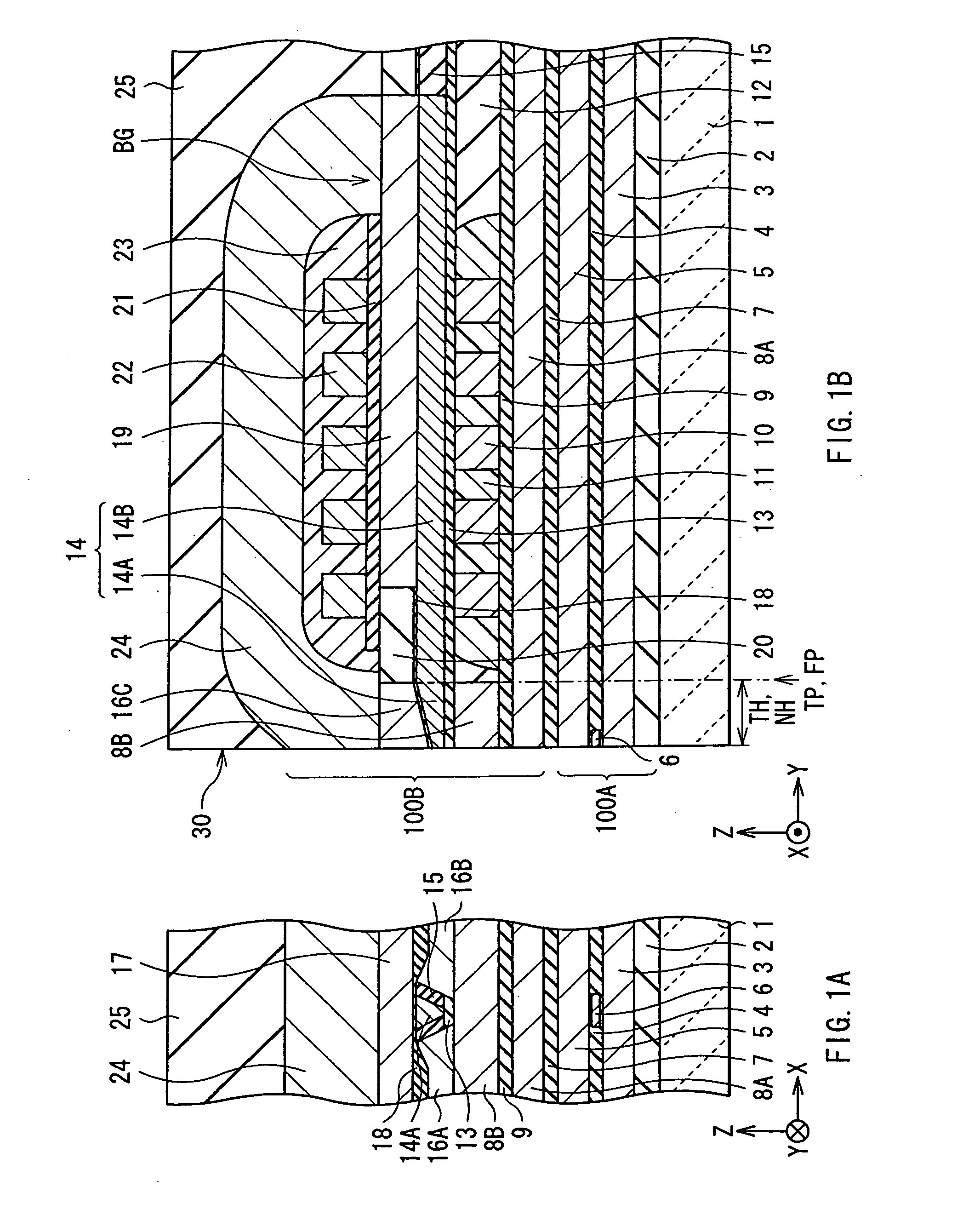
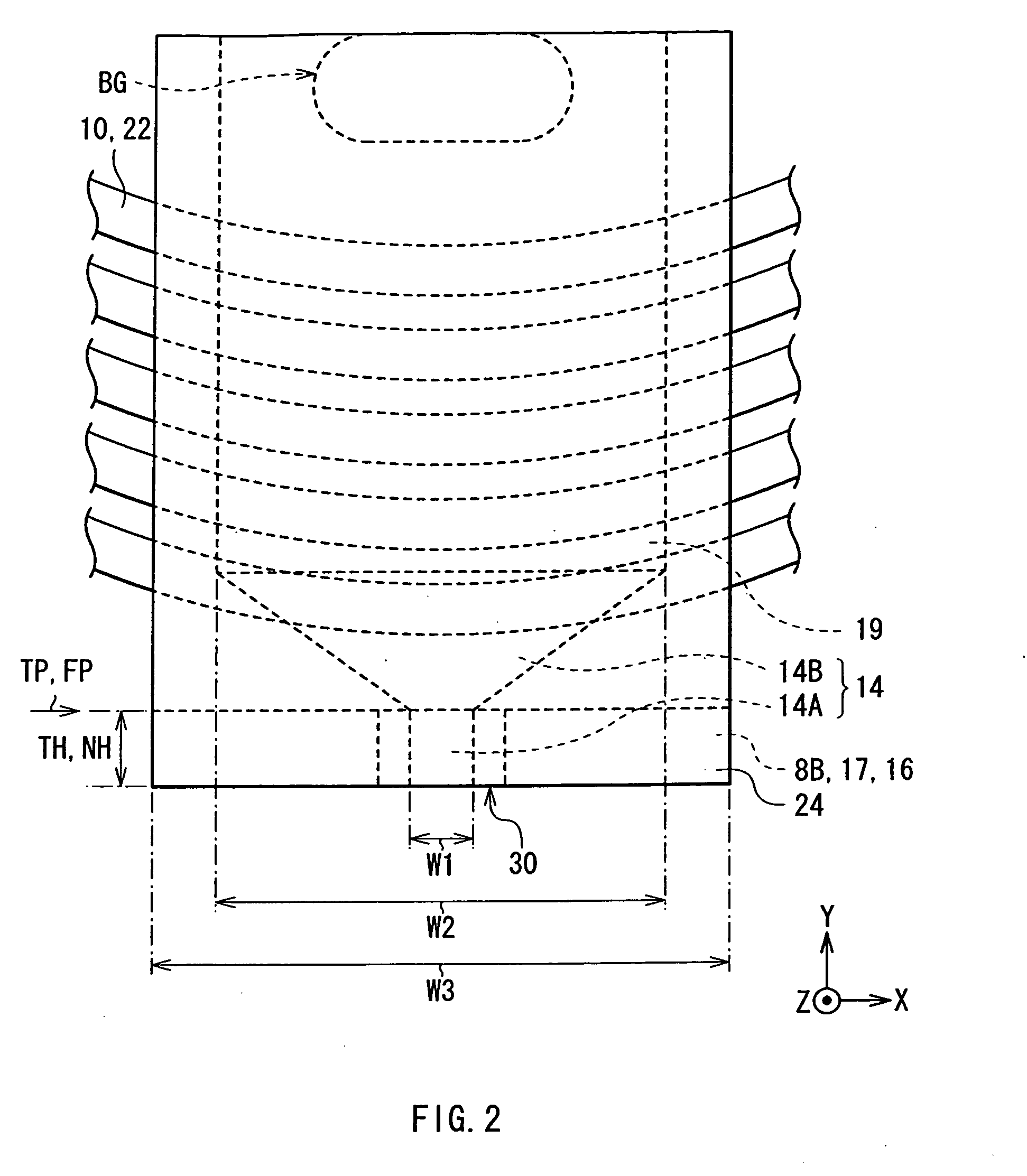
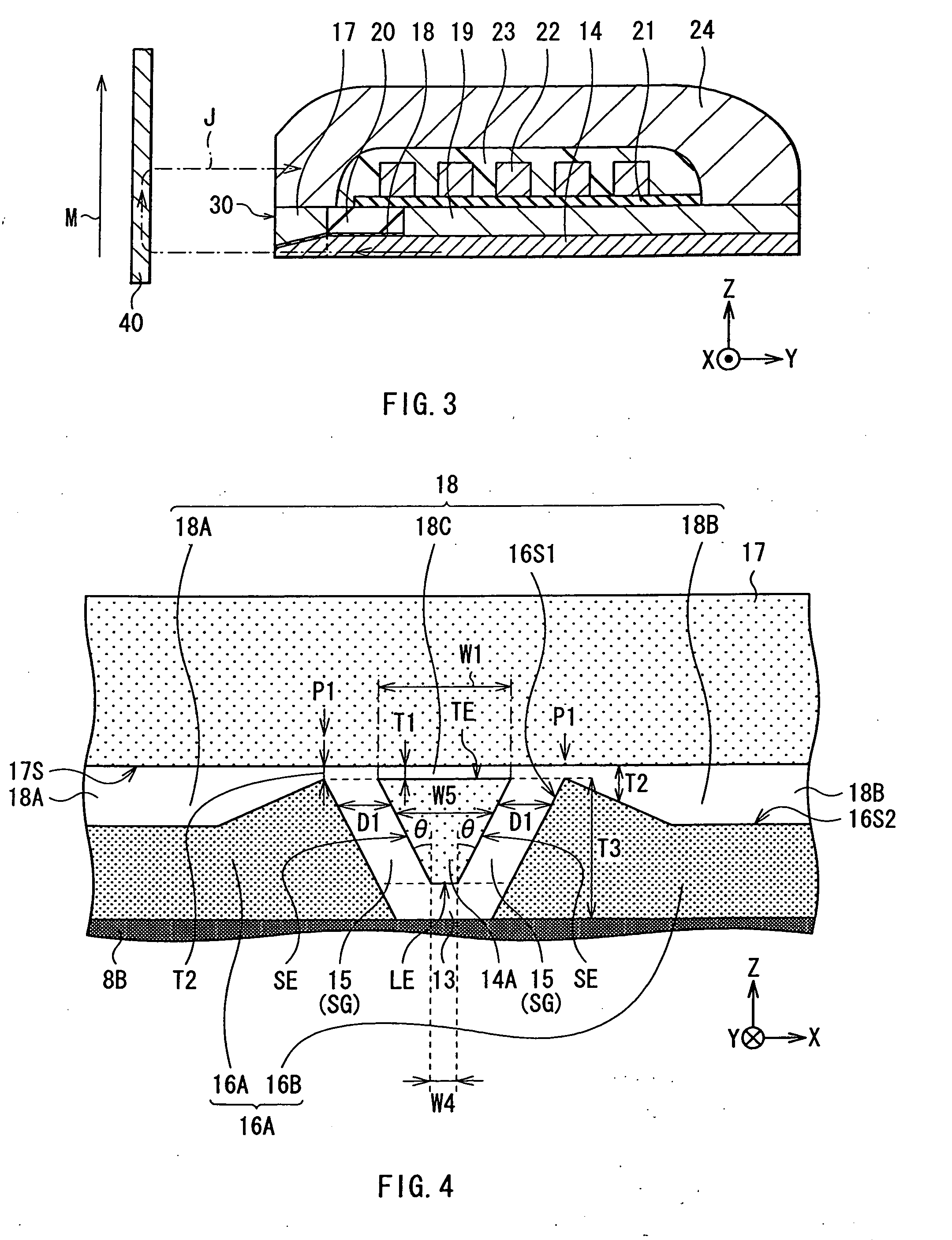
[0106]In the thin-film magnetic head according to the present embodiment, the tip portion 14A, the pair of side shields 16A, 16B, and the trailing shield 17 are mutually separated by the side gap 15 or the trailing gap 18. Moreover, in the trailing gap 18, the wing portions 18A, 18B which separate the side shields 16A, 16B from the trailing shield 17 have the thickness equal to or more than the thickness of the central portion 18C which separates the trailing edge TE of the tip portion 14A from the trailing shield 17. These make it likely for the spread component to be absorbed in the portion in the vicinity of the trailing edge TE in the side shields 16A, 16B, and make it less likely for the magnetic flux to be excessively absorbed in the portions except for the portion in the vicinity of the trailing edge. As a result, realized are both ensuring the magnitude in the recording magnetic field and suppressing the spread of the recording magnetic field, allowing for the improvement in the recording performance.
[0107]In detail, in the recording processing of the perpendicular magnetic recording method, the magnetic flux flowing inside the main magnetic-pole layer 14 is narrowed at the flare point FP, as described above, and then, flows into the tip portion 14A, so that the magnetic flux is likely to spread in the vicinity of the tip portion 14A. Such tendency is prominent especially in the vicinity of the trailing edge TE. In order to suppress the spread of the recording magnetic field, it is effective to sufficiently absorb the spread component of the magnetic flux with the side shields 16A, 16B, by arranging the side shields 16A, 16B close to the tip portion 14A in the write-track width direction. However, in the meanwhile, when the side shields 16A, 16B have the predetermined thickness, the closer to the tip portion 14A the side shields 16A, 16B are arranged, the more the magnitude of the recording magnetic field is reduced. Therefore, like the present embodiment, the side shields 16A, 16B are configured to have the maximum thickness in the vicinity of the tip portion 14A and to include the portion where the thickness reduces with increasing distance from the tip portion 14A, thereby allowing it to suppress the excessive absorption of the magnetic flux and avoid the reduction in the magnitude of the recording magnetic field. In the present embodiment, thus, realized are both ensuring the magnitude of the recording magnetic field and suppressing the spread of the recording magnetic field. Moreover, the recording magnetic field is less likely to reach the adjacent track at the time of recording, so that the adjacent track erase is less likely to occur, and the recording bit pattern is narrowed to have a straight-line shape, so that the quality of the recording bit is improved. Thus, the track density and the linear recording density improve while ensuring the magnitude of the recor

Problems solved by technology

However, the conventional perpendicular magnetic recording head, provided with the side shield, has a trade-off relationship between ensuring the magnitude of the perpendicular magnetic field and suppressing the spread of the perpendicular ma

Method used


Image

  • Perpendicular magnetic recording head and magnetic recording device
  • Perpendicular magnetic recording head and magnetic recording device
  • Perpendicular magnetic recording head and magnetic recording device

Examples


Example

Example

[0119]Next, a specific example according to the present invention will be described in detail.

[0120]The recording performance was examined for the thin-film magnetic head according to the embodiment, illustrated in FIG. 4 (Example 1); the thin-film magnetic heads according to Modifications 1 to 3, illustrated in FIGS. 23 to 25 (Examples 2 to 4); and the thin-film magnetic head according to the comparative example, illustrated in FIG. 30 (Comparative example 1).

[0121]In forming the main part of the thin-film magnetic head according to the embodiment, the tip portion 14A, the leading shield 8B, the trailing shield 17, and the side shields 16A, 16B were formed by growing a plating film of an alloy of iron and cobalt using the electrolytic plating method. At this time, for the tip portion 14A, the thickness was 0.2 μm; the width W1 of the trailing edge TE was 0.09 μm; the width W4 of the leading edge LE was 0.15 μm; and the bevel angle θ was 14 degrees. Alumina was deposited usin...

Example

[0123]For each of the examples and the comparative example, examined were a perpendicular-component magnetic field, the gradient of the perpendicular-component magnetic field, the effective magnetic field which exercises an effect on a track adjacent to the track to be written (the most adjacent track) (ATE (adjacent track erase) effective magnetic field), a perpendicular component of the ATE effective magnetic field, and the WATE effective magnetic field while flowing a predetermined recording current (here, of 40 mA) in the thin-film coils 10, 22, and obtained were the results indicated in Table 1 (each of the items was normalized considering a value of the comparative example as 100%). Among the items indicated in Table 1, as to the perpendicular-component magnetic field and the gradient of the perpendicular-component magnetic field, it is preferable to have a higher value. Meanwhile, as to the ATE effective magnetic field, the perpendicular component of the ATE effective magneti...


PUM


Abstract

A perpendicular magnetic write head includes: a magnetic pole; a pair of side shields on both sides, in a write-track width direction, of the magnetic pole with respective side gaps in between; a trailing shield on a trailing side of the magnetic pole and the pair of side shields with a trailing gap in between. Each of the magnetic pole, the side shield, the trailing shield, the side gap, and the trailing gap has an end face exposed on an air bearing surface. The trailing gap has a first regional part and a second regional part. The first regional part separates a trailing edge of the magnetic pole from the trailing shield, and the second regional part separates the pair of side shields from the trailing shield. All or a part of the second regional part has a thickness larger than a thickness of the first regional part.

Description

BACKGROUND OF THE INVENTION[0001]1. Field of the Invention[0002]The present invention relates to a perpendicular magnetic recording head provided with a magnetic pole and a side shield, and a magnetic recording device mounted with the same.[0003]2. Description of the Related Art[0004]In recent years, with an improvement in an areal recording density of a magnetic recording medium (hereinafter, referred to as “recording medium”) typified by a hard disk, desired is a performance improvement in a magnetic recording head. In response to such a trend, as a recording method of the magnetic head, in substitution for a longitudinal magnetic recording method in which the direction of a signal magnetic field is set to the in-plane direction of the recording medium, attention is attracted to a perpendicular magnetic recording method in which the direction of the signal magnetic field is set to the direction intersecting a plane of the recording medium. The reason why is that there are such adv...

Claims


Application Information

Patent Timeline
IPC IPC(8): G11B5/23
CPCG11B5/1278G11B5/315G11B5/3116
Inventor HIRATA, KEIKURIHARA, KATSUKIANAGAWA, KENKICHIKAGAMI, TAKEO
Owner TDK CORPARATION
Why Eureka
Try Eureka