
Carrier for manufacturing substrate and method of manufacturing substrate using the same

a technology of carrier and substrate, which is applied in the direction of transportation and packaging, mechanical equipment, other domestic objects, etc., can solve the problems of wrinkles, inability to maintain vacuum, and difficulty in continuing a process

Inactive Publication Date: 2011-06-30
SAMSUNG ELECTRO MECHANICS CO LTD
View PDF4 Cites 18 Cited by
  • Summary
  • Abstract
  • Description
  • Claims
  • Application Information

AI Technical Summary

Benefits of technology

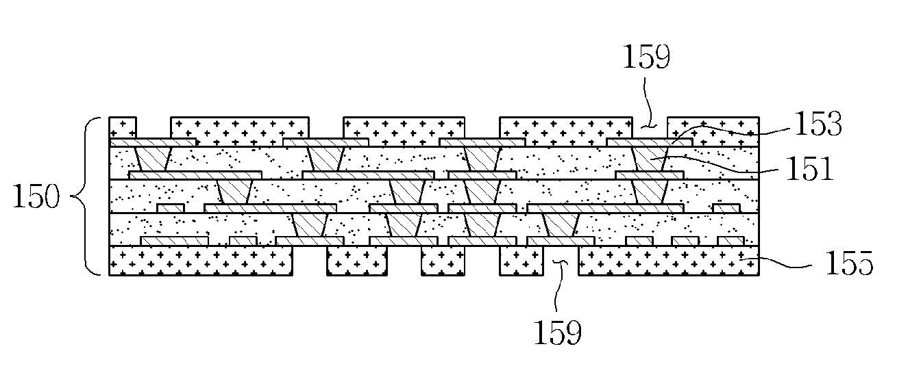
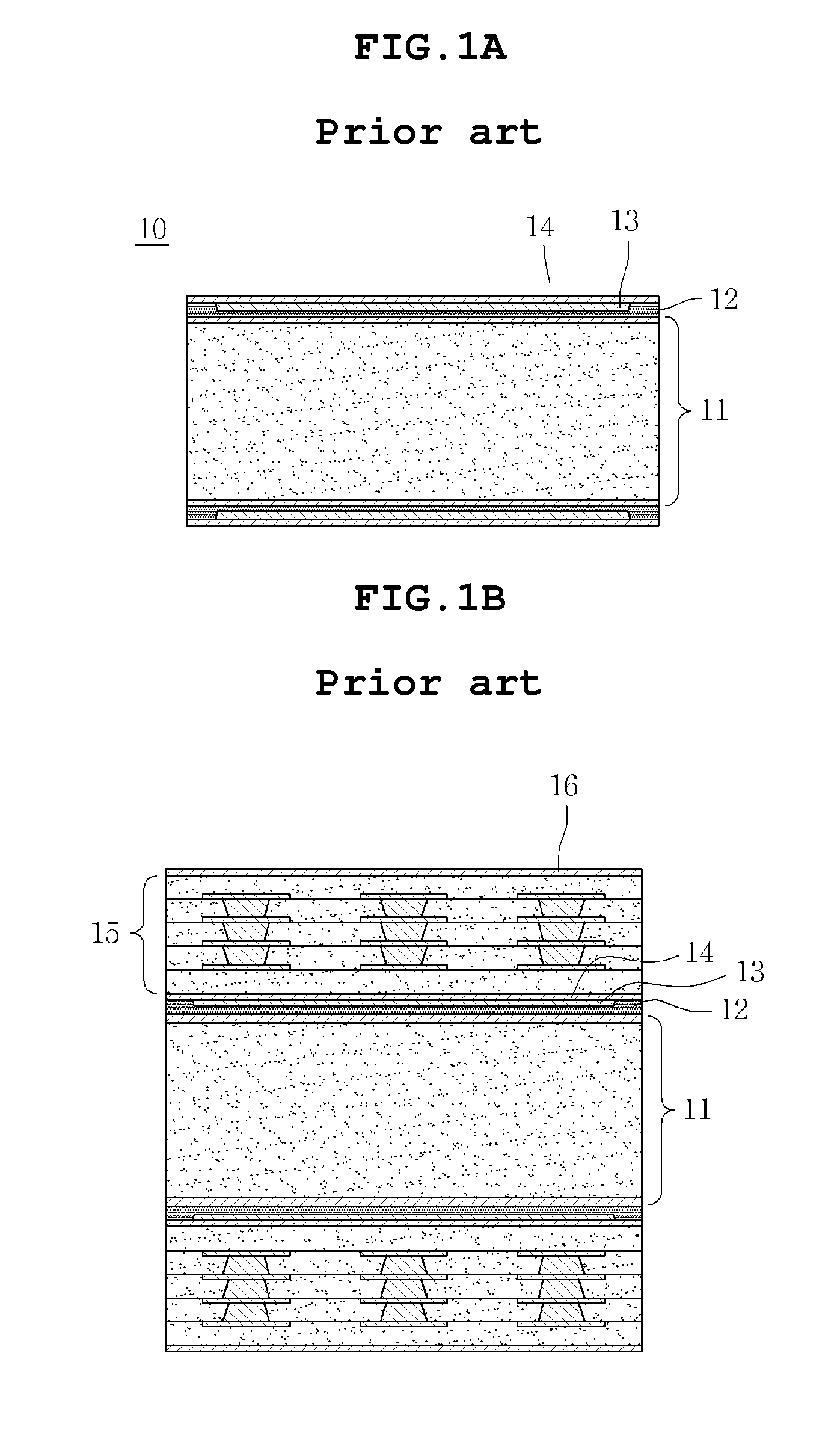
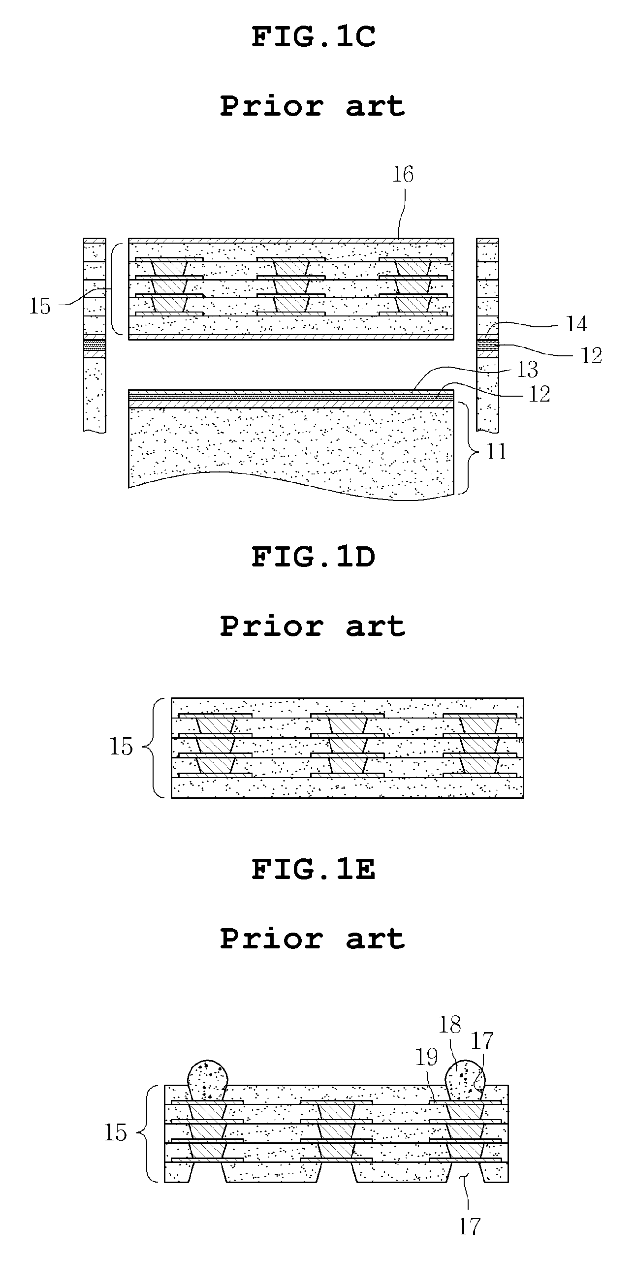
The present invention provides a carrier for manufacturing a substrate that can maintain a vacuum and prevent warping of a build up layer by using an auxiliary adhesive layer and metal layers. The carrier has adhesive layers and auxiliary adhesive layers with lower adhesivity and smaller area than the adhesive layers. The metal layers are attached to the auxiliary adhesive layers and the adhesion between the metal layers and auxiliary adhesive layers is maintained for a predetermined time after the edge of the metal layer is removed. The method of manufacturing a substrate using this carrier involves forming adhesive layers on a base plate, applying a metal layer onto one side of the adhesive layers, heating and pressing the metal layer to bury it in the adhesive layer, and then separating the metal layer from the adhesive layer. The invention provides a solution for manufacturing substrates with improved vacuum maintenance and prevention of warping.

Problems solved by technology

Consequently, there is a problem in that wrinkles occur when the build up layer 15 is formed on the second metal layer 14.
Further, even when pin-holes are formed in the first metal layer 13 or the second metal layer 14, there is a problem in that a vacuum is not maintained between the first metal layer 13 and the second metal layer 14, and thus it is difficult to continue a process.
Therefore, there are problems in that process automation cannot be realized and in that subsequent processes must be manually performed.

Method used


Image

  • Carrier for manufacturing substrate and method of manufacturing substrate using the same
  • Carrier for manufacturing substrate and method of manufacturing substrate using the same
  • Carrier for manufacturing substrate and method of manufacturing substrate using the same

Examples


Embodiment Construction

[0037]The objects, features and advantages of the present invention will be more clearly understood from the following detailed description and preferred embodiments taken in conjunction with the accompanying drawings. Throughout the accompanying drawings, the same reference numerals are used to designate the same or similar components, and redundant descriptions thereof are omitted. Further, in the following description, the terms “one side”, “the other side” and the like are used to differentiate a certain component from other components, but the configuration of such components should not be construed to be limited by the terms. Further, in the description of the present invention, when it is determined that the detailed description of the related art would obscure the gist of the present invention, the description thereof will be omitted.

[0038]Hereinafter, preferred embodiments of the present invention will be described in detail with reference to the attached drawings.

[0039]FIG...


PUM

PropertyMeasurementUnit
thicknessaaaaaaaaaa
adhesivityaaaaaaaaaa
adhesiveaaaaaaaaaa

Abstract

Disclosed herein is a carrier for manufacturing a substrate, including: a base plate; adhesive layers formed on one side or both sides of the base plate; auxiliary adhesive layers, each of which is buried in one side of each of the adhesive layers, has a smaller area than each of the adhesive layers and has lower adhesivity than each of the adhesive layers; and metal layers, each of which is formed on one side of each of the auxiliary adhesive layers, whose edges are attached to the adhesive layers, and whose other portions excluding the edges are attached to the auxiliary adhesive layers. The carrier is advantageous in that a metal layer and an auxiliary adhesive layer are attached to each other by the adhesivity of the auxiliary adhesive layer, so that it is not required to use vacuum adsorption, with the result that a process of manufacturing a substrate can be performed more stably.

Description

CROSS REFERENCE TO RELATED APPLICATION[0001]This application claims the benefit of Korean Patent Application No. 10-2009-0133970, filed Dec. 30, 2009, entitled “A carrier member for manufacturing a substrate and a method of manufacturing a substrate using the same”, which is hereby incorporated by reference in its entirety into this application.BACKGROUND OF THE INVENTION[0002]1. Technical Field[0003]The present invention relates to a carrier for manufacturing a substrate and a method of manufacturing a substrate using the same.[0004]2. Description of the Related Art[0005]Generally, printed circuit boards (PCBs) are manufactured by patterning one or both sides of a substrate, composed of various thermosetting resins, using copper foil, and disposing and fixing ICs or electronic parts on the substrate to form an electric circuit and then coating the substrate with an insulator.[0006]Recently, with the advancement of the electronics industry, electronic parts are increasingly required...

Claims


Application Information

Patent Timeline
Patent Type & Authority Applications(United States)
IPC IPC(8): B32B7/12B32B38/10B32B38/00B32B37/02
CPCB32B2457/08H05K3/0097H05K3/4682H05K2203/1536Y10T428/2804H05K13/04Y10T156/1142Y10T156/1043H05K2203/1572H05K3/46
Inventor KIM, JIN HOAHN, JIN YONGKIM, KI HWANKIM, BYUNG MOONLEE, SEOK KYU
Owner SAMSUNG ELECTRO MECHANICS CO LTD
Learn More