Radio base station, radio terminal device, radio relay station device, transmission power control method, radio communication relay method, and radio communication system

a radio relay and relay station technology, applied in the field of radio communication system, can solve the problems of terminals not being able to receive the signal (down signal) from the relay station, attenuation due to transmission distance increase as the distance increases, and possible collisions between multiple terminals, so as to improve the utilization effect of resources and suppress the increase in delay

Inactive Publication Date: 2011-06-30
PANASONIC CORP
View PDF8 Cites 68 Cited by
  • Summary
  • Abstract
  • Description
  • Claims
  • Application Information

AI Technical Summary

Benefits of technology

The present invention has been made under the background described above. It is an object of the present invention to provide a radio base station d

Problems solved by technology

In this case, since terminals try to communicate with the network by using an RACH which is a common channel at any time, collisions may possibly take place between multiple terminals.
However, when a high-frequency radio band is utilized, while a high transmission rate can be expected at short distances, attenuation due to transmission distance increases as the distance increases.
However, as described above, since the terminal is located out of the communication cell of the relay station, the terminal cannot receive the signal (downward signal) from the relay station.
However, when the terminal is located at an edge portion (portion of the border) of the communication cell of the base station, there is a chance that the random access preamble does not reach the base station.
In that case, even if the random access preamble does not directly reach the base station (for example, the transmission power is insufficient), the terminal cannot recognize that.
For example, in a system in which the termi

Method used


Image

  • Radio base station, radio terminal device, radio relay station device, transmission power control method, radio communication relay method, and radio communication system
  • Radio base station, radio terminal device, radio relay station device, transmission power control method, radio communication relay method, and radio communication system
  • Radio base station, radio terminal device, radio relay station device, transmission power control method, radio communication relay method, and radio communication system

Examples


Embodiment Construction

Hereafter, the present invention will be described in detail. However, the detailed description below and the appended drawings will not limit the invention. Instead, the scope of the invention is defined by the appended claims.

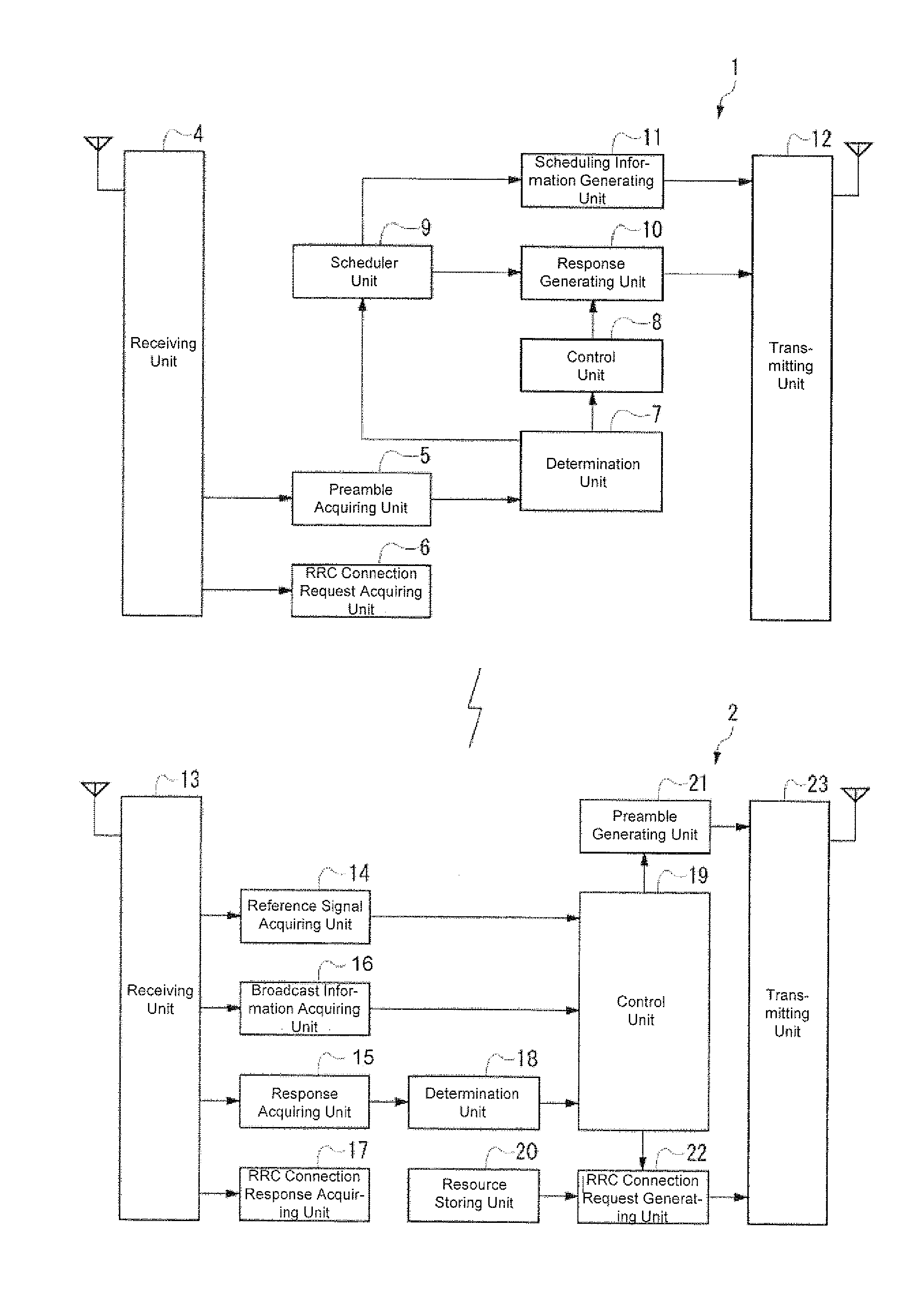
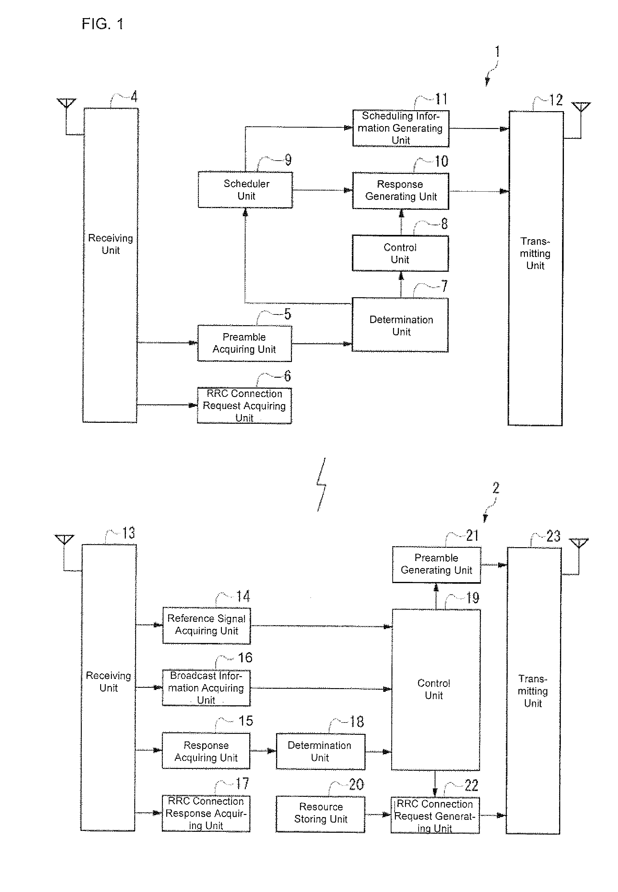
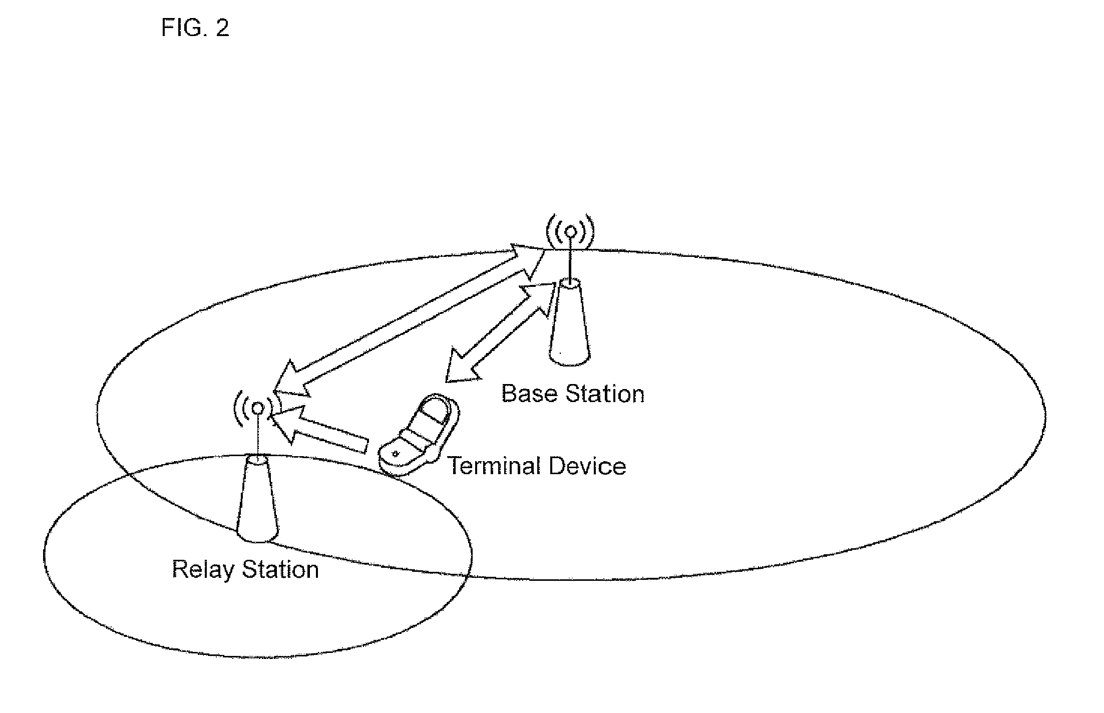
The radio base station device of the present invention is a radio base station device to be used in a base station in a radio communication system in which a relay station for relaying radio communication between the base station and a terminal is disposed in a communication cell of the base station, wherein a different resource is allocated to each of the terminal and the relay station as a resource for communication with the base station, the radio base station device comprising: a preamble receiving unit for receiving a random access preamble transmitted from the terminal; a relay determination unit for determining whether or not relaying of the random access preamble has been performed, based on resource information included in the random access preamble;...


PUM


Abstract

A different resource is allocated to each of a terminal and a relay station as a resource for the communication with a base station. A radio base station device (1) provided in the base station includes: a determination unit (7) which determines whether or not relaying of a random access preamble is performed based on the resource information included in the random access preamble; and a response generating unit (10) which generates a random access response to which relay flag information is attached. When the random access response with the relay flag information attached is transmitted from the base station to the terminal, the control of the transmission power of an RRC connection request is performed at the terminal based on the relay flag information. This allows for the suppression of increase in the delay before the establishment of RRC connection, and thereby a radio base station device which improves the utilization effect of resources is provided.

Description

TECHNICAL FIELD The present invention relates to a radio communication system in which a base station, a terminal, and a relay station for relaying radio communication are provided, and particularly to a technique of controlling the transmission power of the terminal depending on whether or not relaying is performed.BACKGROUND ART Conventionally, a network system is known in which radio communication is performed between a base station and a terminal. In such a conventional system, a procedure called an RACH procedure is performed when the terminal is shifted from an idle state to a call procedure. For example, International Publication No. WO05 / 034554; Japanese Patent Laid-Open No. 2001-560555; 3GPP TS36.300 “E-UTRA and E-UTRAN Overall description stage 2”; 3GPP TSG RAN WG1 meeting #46bis R1-062556, “RACE Design Issues of Large Cell Deployment”, LG Electronics; 3GPP TSG RAN 36.221:E-UTRA MAC Protocol Specification; 3GPP TSG RAN 36.213:5-UTRA Physical Layer Procedure; 3GPP TSG RAN W...

Claims


Application Information

Patent Timeline
IPC IPC(8): H04B7/14
CPCH04B7/15528H04B7/2606H04W52/46H04W84/047H04W74/002H04W74/0833H04W52/50
Inventor BINTI HARUM, NORHARYATIISHII, YOSHIKAZUKANAZAWA, TAKESHI
Owner PANASONIC CORP
Why Eureka
Try Eureka