Structure for coupling differential assembly with drive shaft

a technology of differential assembly and drive shaft, which is applied in mechanical equipment, transportation and packaging, and transportation of goods, etc., can solve the problem of not being able to couple the drive shafts using the stopper disk, and achieve the effect of preventing the play of the coupling head, preventing looseness between the coupling heads, and being easy to rota

Active Publication Date: 2011-06-30
CUSCO JAPAN
View PDF4 Cites 7 Cited by
  • Summary
  • Abstract
  • Description
  • Claims
  • Application Information

AI Technical Summary

Benefits of technology

[0030]According to the invention set forth in claim 5, the coupling head to be attached to the end of the drive shaft can be easily made rotatable with respect to the drive shaft. It is thus possible to prevent the drive shaft and the pinion shaft to be integrally coupled with each other, ensuring the operation of the differential gear mechanism that is composed of the pair of right and left side gears, the pinion gears, the pinion shafts and the like.
[0031]According to the invention set forth in claim 6, the shaft hole of the sleeve member has such an inner diameter which is tight and just enough for the coupling shaft, to pass through. This configuration allows for attaching the coupling shaft to the pinion shaft body without looseness even when the through hole of the pin

Problems solved by technology

It is thus not possible to couple the

Method used


Image

  • Structure for coupling differential assembly with drive shaft
  • Structure for coupling differential assembly with drive shaft
  • Structure for coupling differential assembly with drive shaft

Examples


Embodiment Construction

[0038]Now, the present invention will be described below in more detail with reference to the accompanying drawings in accordance with an embodiment.

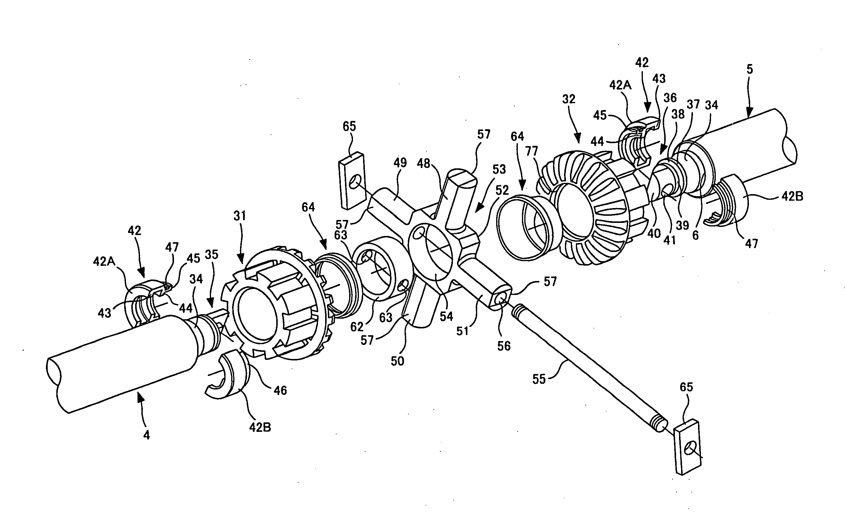
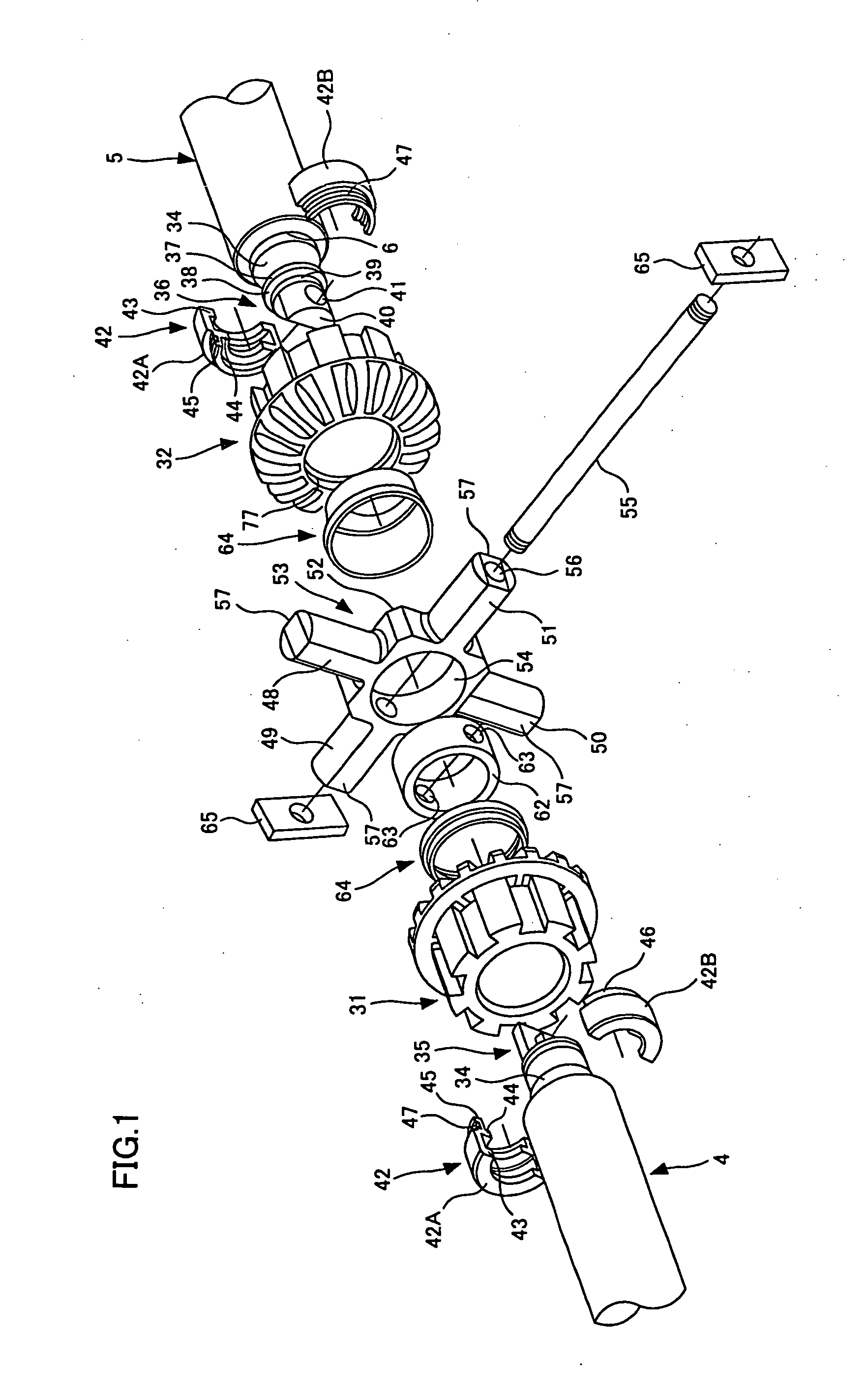
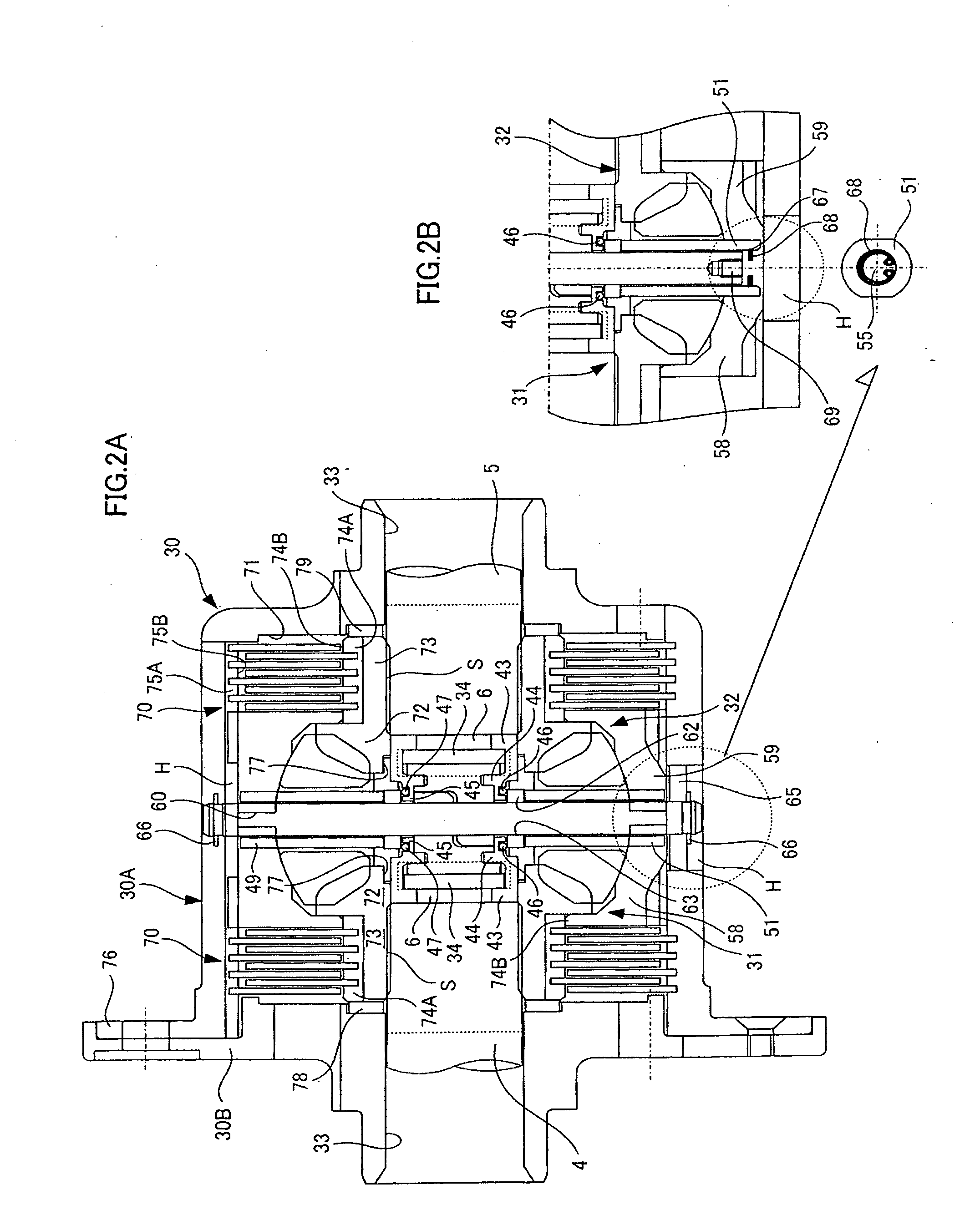
[0039]FIG. 1 is an exploded perspective view illustrating a coupling structure for a differential assembly and drive shafts according to an embodiment of the present invention. FIG. 2A is a longitudinal sectional view illustrating a differential assembly formed in the coupling structure of FIG. 1. FIG. 28 is a view illustrating another stopper structure for a coupling shaft.

[0040]Although not illustrated in FIG. 2A, the differential assembly is composed of a differential carrier 15 shown in FIG. 3. The assembly also includes long right and left drive shafts 4 and 5 to maintain the distance L between the tires. Note that the right and left drive shafts 4 and 5 have splines S formed on their end portion, and the splines S of the drive shafts 4 and 5 are to be engaged with those splines formed on the shaft hole of right and left side gears...


PUM


Abstract

A coupling structure is provided which can be used even when drive shafts cannot be provided on their end with a stopper. The coupling structure allows the drive shafts to be coupled to a differential assembly, requiring a manipulation only from outside the differential case to assure that the drive shafts are coupled to each other so as not to be movable in the direction of the axle shaft. The coupling structure includes a pair of right and left coupling heads and a coupling shaft. Each of the coupling heads has a coupling hole at the point of intersection of the axial line of pinion shafts provided in the differential assembly and the axial line of a pair of right and left drive shafts. The coupling heads are added to the drive shafts via a connector, respectively, to be rotatable about the axle shaft and not movable in the direction of the axle shaft, with the end portion of the coupling heads being disposed in a coupling ring of a cross shaft. The coupling shaft penetrates the through holes of the pair of pinion shafts and the coupling holes of the pair of right and left coupling heads.

Description

BACKGROUND OF THE INVENTION[0001]1. Field of the Invention[0002]The present invention relates to a structure for coupling a differential assembly installed in an automobile with the right and left drive shafts connected to the right and left traction wheels. More particularly, the invention relates to a limited slip differential assembly.[0003]2. Description of the Related Art[0004]The power transmission mechanism of vehicles includes a differential assembly through which power is transmitted and the right and left drive shafts which transfer the drive force supplied to the differential assembly to the right and left traction wheels, respectively.[0005]The differential assembly includes a differential carrier mounted on the vehicle body and a differential case installed inside the differential carrier. The differential case has the right and left end portions that are rotatably supported by the differential carrier, for example, via bearings. Accordingly, the differential case is pr...

Claims


Application Information

Patent Timeline
IPC IPC(8): F16H48/20F16H48/08F16H48/22F16H48/38
CPCF16H48/08F16H2048/282F16H2048/085F16H48/22
Inventor HONDA, TORU
Owner CUSCO JAPAN
Why Eureka
Try Eureka