Systems for designing a foot orthotic

a technology for foot and orthotic, applied in the direction of instruments, insoles, force/torque/work measurement devices, etc., can solve the problems of little to no standardization in the methods used to treat mechanically induced foot pain, dissipation of the force required, and inability to control the mechanics of the foot with accommodative orthosis made of eva and similar soft materials

Inactive Publication Date: 2011-07-07
TENSEGRITY TECH
View PDF62 Cites 10 Cited by
  • Summary
  • Abstract
  • Description
  • Claims
  • Application Information

AI Technical Summary

Benefits of technology

In other embodiments, the system can comprise a means for transmitting the digital anatomy to a remote location. In other embodiments, the computer program can comprise executable instructions that obtain a digital anatomy of a foot; analyze the digital anatomy to evaluate the relationship between two or more bones in the foot; determine an adjustment to one or more tarsal bones; and send a signal to one or more moveable gauging elements on the bed to effect movement of one or more gauging elements to fabricate an orthotic device for achieving the repositioning of one or more bones.

Problems solved by technology

Prior to about 1950, there was little to no standardization in the methods used to treat mechanically-induced foot pain.
This cushioning also results in some dissipation of the forces required for efficient gait that ordinarily would be transmitted up the kinetic chain.
In addition to force dissipation, accommodative orthosis made of EVA and similar soft materials are unable to control foot mechanics.
This is problematic because the foot must be allowed to continually adapt to the ground in order to operate efficiently.
Such orthotics abnormally maintain the foot's arch throughout gait, with the orthosis supporting the body's weight and compressing the soft tissue between the bones and the orthosis.
While functional and accommodative orthotics may temporarily decrease foot pain due to restricting pathologic range of motion and in cushioning the foot, they necessarily cause pathologic gait, and this approach will inevitably cause pain in other joints in the foot, leg, pelvis and / or back as they compensate for this abnormal motion.

Method used


Image

  • Systems for designing a foot orthotic
  • Systems for designing a foot orthotic
  • Systems for designing a foot orthotic

Examples


example 1

Measurement of a Patient's Foot to Obtain a Digital Anatomy

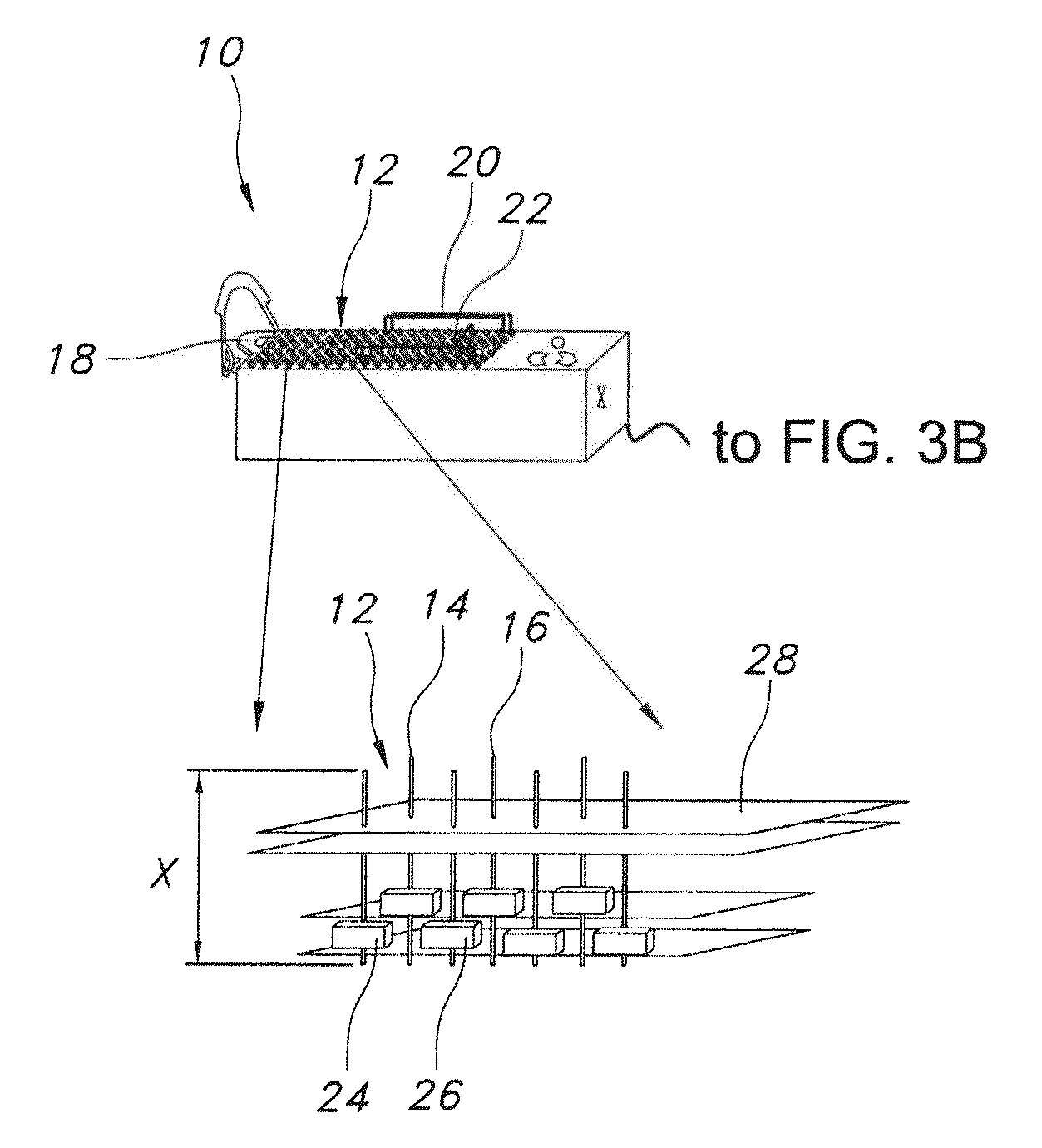
A patient experiencing pain in the left foot during physical activity is provided. The patient is seated and her bare foot is placed, under minimal weight-bearing conditions, on a foot platform having a pin bed comprised of an array of independently moveable pins. The pins within the pin bed are moved up toward the plantar surface of the foot by means of servos under control of a computer. A baseline reading of the patient's foot is acquired with the pins gently touching the plantar surface of the foot. The “ball” of the heel and first and fifth metatarsal heads ideally results in 0.0 mm pin elevation. In some embodiments, the pins are flush with the surface of the bed with the baseline reading taken when a small amount of pressure (that will not displace any soft (issue) is applied to the pins to elevate them just enough to touch the plantar surface of the foot. Pin height is displayed in small increments (0.10 to 0.05 mm) ...

example 2

Analysis of a Digital Anatomy

A patient's foot is placed on a foot platform comprising a pin bed. A pressure is applied to the pins in the bed to compress the soft tissue on the plantar surface of the foot to create a uniform density of tissue per cubic centimeter at each pin head surface. The computer program collects pin height for each pin and analyzes the information to determine bone positions of the foot, first assessing the shape of the interior surface of the calcaneus. As seen in FIG. 4A, the inferior surface of the calcaneus in a healthy or restored foot is a circular shape. If the calcaneus is not in an ideal position, the shape will appear as an oval indicating that the calcaneus is plantar flexed, as visible in the contour plot of the foot in FIG. 5A. The computer then uses this data to conduct an analysis of the foot, using the following exemplary technique based on the digital image shown FIG. 6A.

The computer constructs four lines starting with an image of scanned foot...

example 3

Analysis of a Digital Anatomy

A digital anatomy of a foot is obtained as described in Example 1. Three series of calculations are performed by the system software to design a restorative foot orthotic device.

First, the calcaneocuboid (CC) and LCNC congruencies are calculated by drawing and evaluating several lines which transect 1) the long axis of the calcaneus footprint, 2) the axis formed from the bisection of the proximal and distal surfaces of the cuboid, 3) the space between the fourth and fifth rays (which will exhibit a deviation if the calcaneocuboid joint is dysfunctional). Additionally, a reduction line is drawn through the curve of the metatarsal heads that should bisect a line going through the lateral column in a nearly perpendicular fashion. Second, the software program defines the angle of the calcaneus and defines the heel cup. Third, the software program delineates the area under the midfoot to be supported by LCNC Dynamic Post, now to be described with reference to...


PUM


Abstract

Disclosed are methods and systems for design of a foot orthotic, and a foot orthotic device designed in accord therewith. More specifically described is an individualized foot orthotic device to correct and/or restore the ideal alignment and/or positioning of foot structures. In the method, sequential pressure is applied to regions on a plantar foot surface, and positional information is obtained about each region. Based on the positional information, an orthotic profile is determined, for design of one or more custom, individualized foot orthotic devices for a subject.

Description

TECHNICAL FIELDThe subject matter described herein relates to systems for the design of a foot orthotic and to a foot orthotic designed using the system. More particularly, the subject matter is directed to systems that obtain and utilize a digital anatomy of one or more structures in a foot of a patient for the design of one or more custom foot orthotics, to be used, in some embodiments, in a restorative treatment plan.BACKGROUNDFoot orthotics are typically designed based on an image of the plantar surface of a patient's foot. Standard foot orthotics attempt to treat foot or arch pain by providing cushioning, stability or support, sometimes attempting to adjust or stabilize movement about the subtalar joint. Prior to about 1950, there was little to no standardization in the methods used to treat mechanically-induced foot pain. A standardized approach to the design of foot orthoses was introduced in 1954, when Merton L. Root, DPM, revolutionized the field with the theory of the Subt...

Claims


Application Information

Patent Timeline
Patent Type & Authority Applications(United States)
IPC IPC(8): A61F5/14A61B5/107
CPCA43B7/141A43B7/142A43D1/022A61B5/1036A61B5/4528G06F17/50A61B2562/046A61F5/14A43B13/38A43D1/02A61B2562/0247G06F30/00G06F30/20G06F30/10A43B7/144A43B7/1445A43B13/386A43B17/006
Inventor MILLER, J. KEVINBEIDLEMAN, NEAL J.BOENNIGHAUSEN, MICHAEL A.LATTERMAN, MICHAEL S.FREEBURY, GREGG E.LATTERMAN, SUE ANNWEN, HUAFENG
Owner TENSEGRITY TECH
Why Eureka
Try Eureka