Modular head inserter

a modular head and inserter technology, applied in the field of orthopedic surgery, can solve the problems of loss of stability of the intervertebral, pressure needed during the installation step, and conditions where the spine needs to be stabilized

Active Publication Date: 2017-04-11
SPINAL
View PDF25 Cites 15 Cited by
  • Summary
  • Abstract
  • Description
  • Claims
  • Application Information

AI Technical Summary

Benefits of technology

[0008]An objective of the invention is to provide a modular head (tulip) inserter that can cance

Problems solved by technology

Chronic back problems are caused by intervertebral disc disease and deterioration and loss of stability of the intervertebral joints.
Severe trauma to the back can furth

Method used


Image

  • Modular head inserter
  • Modular head inserter
  • Modular head inserter

Examples


Embodiment Construction

[0047]Detailed embodiments of the instant invention are disclosed herein; however, it is to be understood that the disclosed embodiments are merely exemplary of the invention, which may be embodied in various forms. Therefore, specific functional and structural details disclosed herein are not to be interpreted as limiting, but merely as a basis for the claims and as a representation basis for teaching one skilled in the art to variously employ the present invention in virtually any appropriately detailed structure.

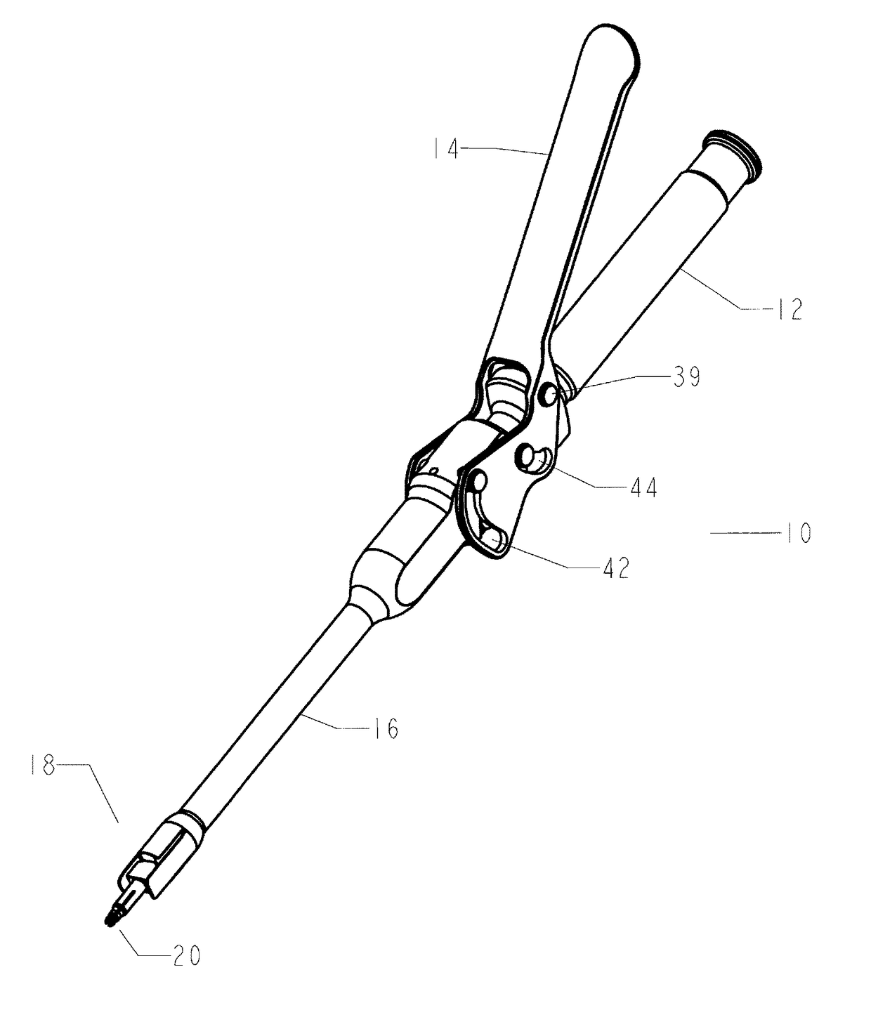
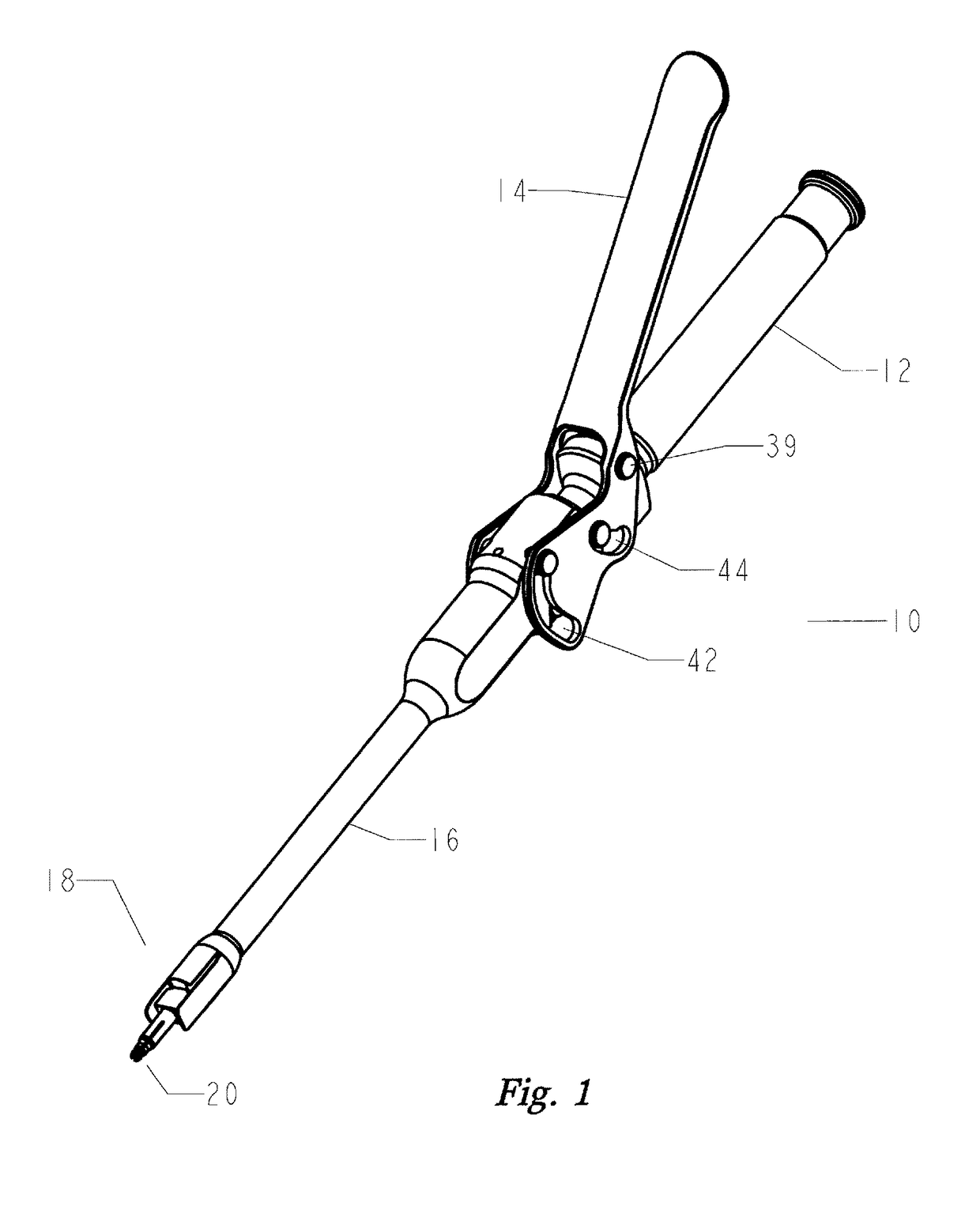
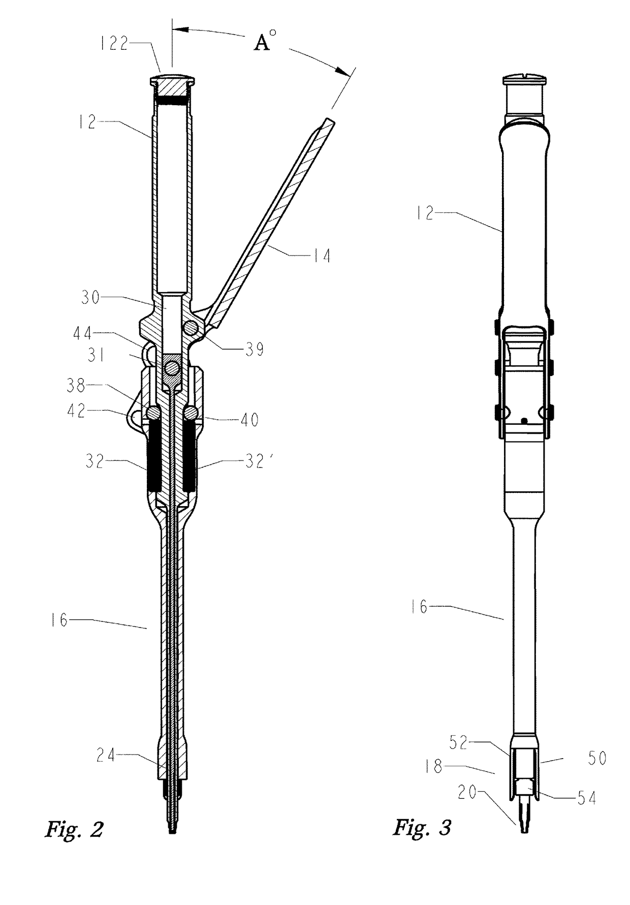
[0048]Referring to FIGS. 1-3, set forth is the modular head inserter instrument 10, having a body 12 with a lever handle 14 and push sleeve 16. At a distal end 18 of the push sleeve 16 is a collet tip 20 used for temporary coupling to a relieve groove in a bone screw. The push sleeve 16 houses an expander pin 24 for insertion through the collet tip 20. The collet tip 20 is driven by the expander pin head 110 that can slide within the cavity passageway 30. The expander pin...


PUM


Abstract

Disclosed is an instrument to assist in installing bottom loading orthopedic devices. The orthopedic devices are used to fix and stabilize bones to correct anomalies in skeletal structure occurring naturally or by trauma. Bone screws are anchored and tulips by the disclosed instrument wherein push/pull forces are equalized to eliminate the imposition of stress on the skeletal of individual.

Description

CROSS REFERENCE TO RELATED APPLICATIONS[0001]This patent application is related to U.S. patent application Ser. No. 14 / 643,448, the contents of which are incorporated herein by reference.FIELD OF THE INVENTION[0002]This invention relates to orthopedic surgery and, in particular, to an instrument for securing a modular head assembly.BACKGROUND OF THE INVENTION[0003]Chronic back problems are caused by intervertebral disc disease and deterioration and loss of stability of the intervertebral joints. Examples of these spinal conditions include degenerative disc disease, scoliosis, spondylolisthesis, spinal stenosis, etc. Stabilization and / or arthrodesis of the intervertebral joint can reduce the pain associated with movement of a diseased or deteriorated intervertebral joint. In order to allow for development of a solid intervertebral fusion, the spine has to be stabilized. Severe trauma to the back can further cause conditions wherein the spine needs to be stabilized. There are many ins...

Claims


Application Information

Patent Timeline
IPC IPC(8): A61B17/58A61B17/70
CPCA61B17/7076A61B17/7037
Inventor DOUBLER, ROBERT L.HAMMILL, SR., JOHN E.
Owner SPINAL
Why Eureka
Try Eureka