Method for manufacturing a metal composite component, in particular for an electromagnetic valve

a technology of metal composite components and electromagnetic valves, which is applied in the direction of magnets, magnetic materials, magnetic bodies, etc., can solve the problems of fundamentally difficult shape or deep draw of materials, and achieve the effect of reducing saturation polarization and simple and inexpensive manner

Inactive Publication Date: 2011-07-07
ROBERT BOSCH GMBH
View PDF7 Cites 7 Cited by
  • Summary
  • Abstract
  • Description
  • Claims
  • Application Information

AI Technical Summary

Benefits of technology

[0007]The method according to the present invention for manufacturing a metal composite component has the advantage that a magnetic separation is implementable on a one-piece, e.g., sleeve-shaped composite component having narrowly limited transitional areas in a particularly simple and inexpensive manner suitable for reliable, large-scale industrial manufacturing. The composite component manufactured according to the present ...

Problems solved by technology

These materials are fundamentally difficult to shape or to deep draw b...

Method used


Image

  • Method for manufacturing a metal composite component, in particular for an electromagnetic valve
  • Method for manufacturing a metal composite component, in particular for an electromagnetic valve
  • Method for manufacturing a metal composite component, in particular for an electromagnetic valve

Examples


Embodiment Construction

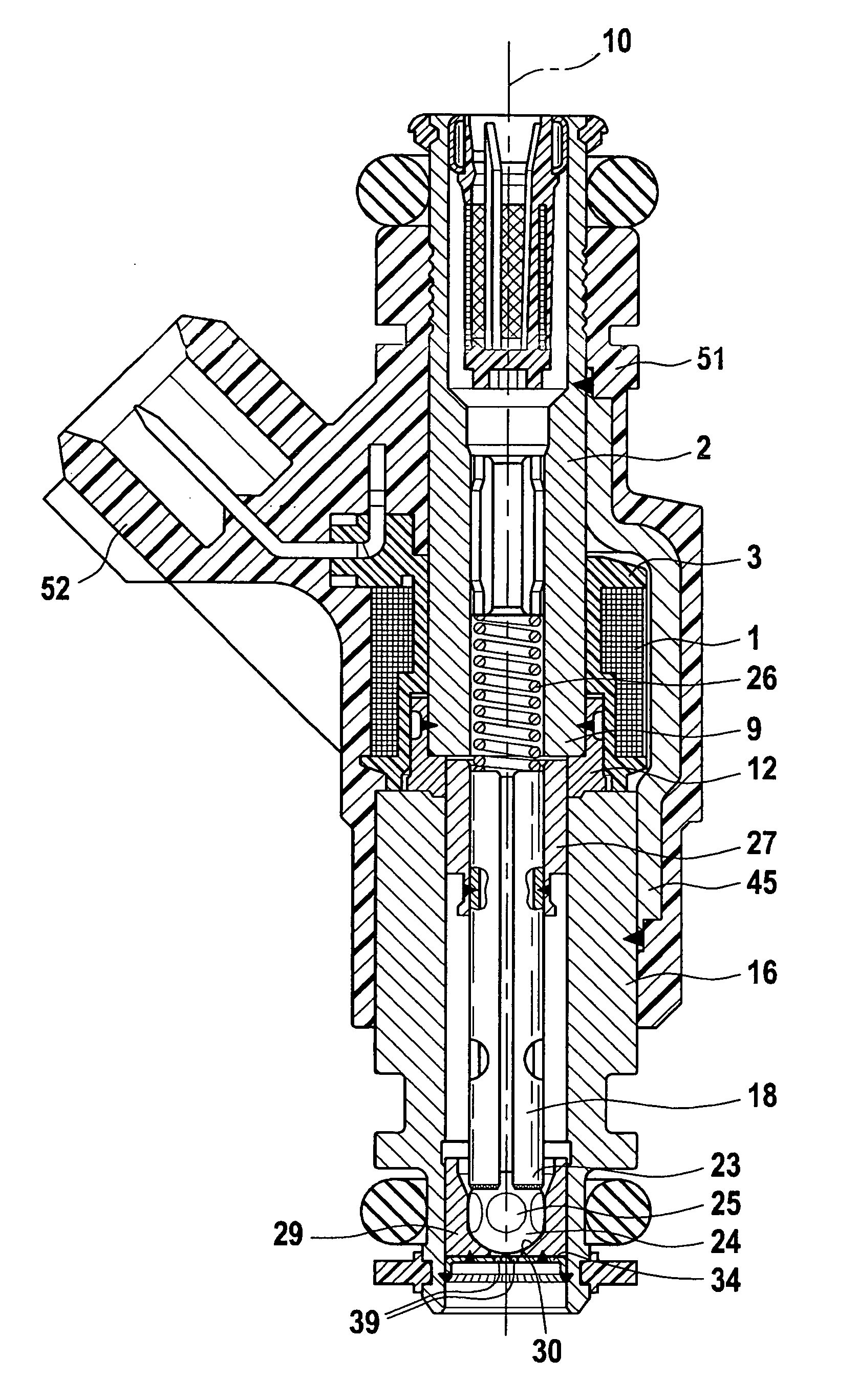
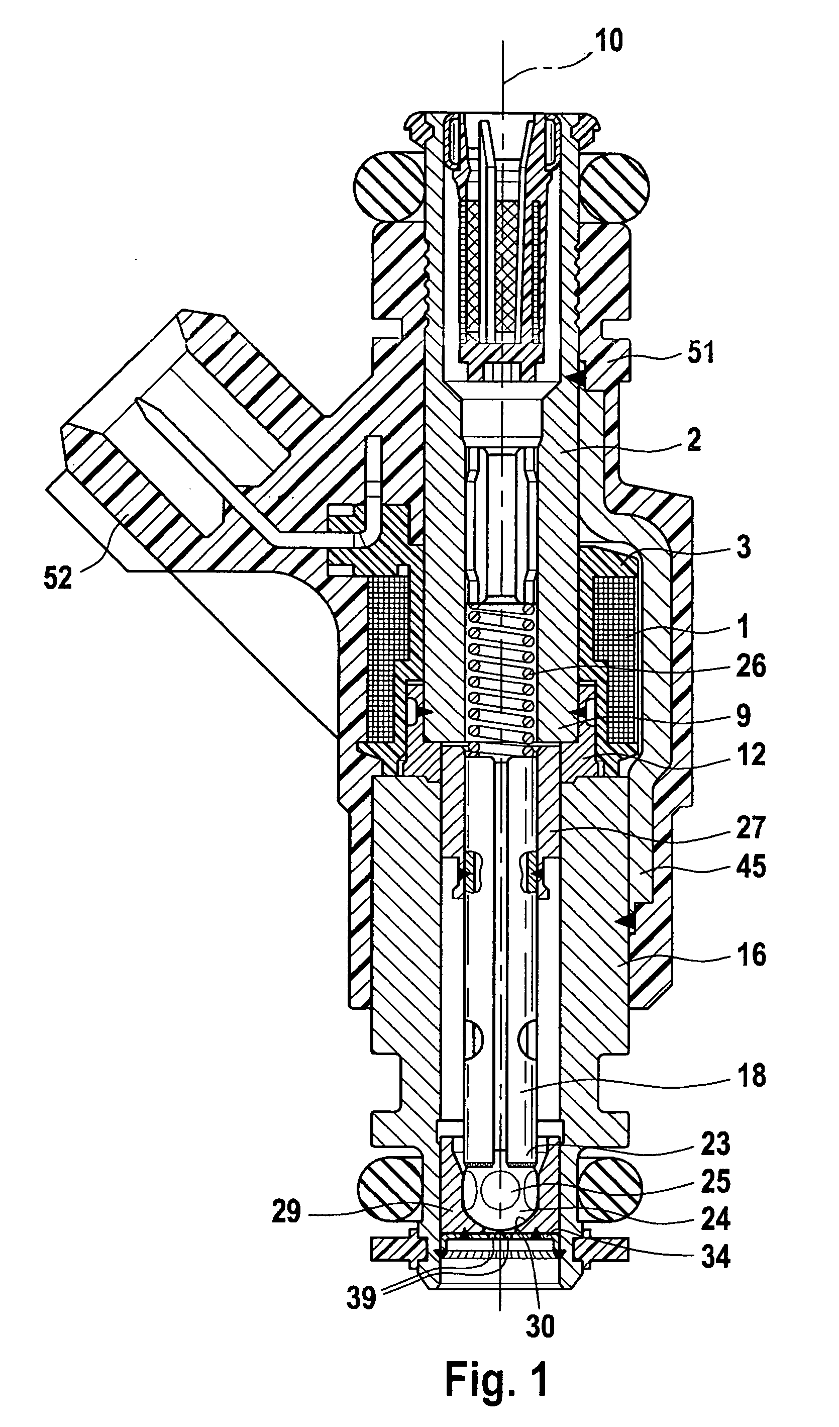
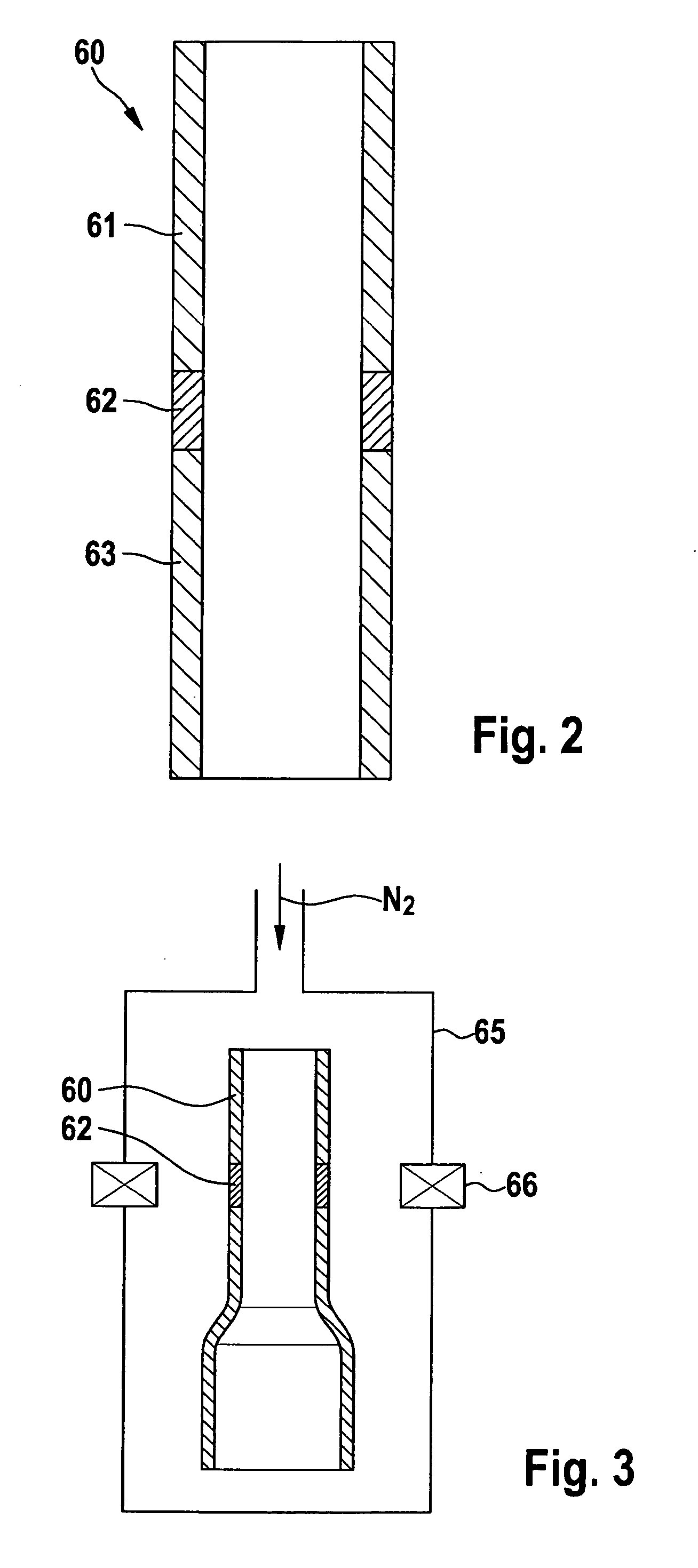
[0018]Before describing the characteristics of metal composite component 60 manufactured according to the present invention on the basis of FIGS. 2 and 5, a fuel injector of the related art will be explained in greater detail on the basis of FIG. 1 as a possible starting product for such a composite component 60.

[0019]The electromagnetically operable valve shown in FIG. 1 as an example in the form of an injector for fuel injection systems of mixture-compressing, spark-ignition internal combustion engines has a tubular core 2, which acts as a fuel inlet connection and internal pole; it is surrounded by solenoid 1 and has a constant outside diameter over its entire length, for example. A coil body 3, which is stepped in the radial direction, accommodates a winding of solenoid 1 and allows a compact design of the injector in the area of solenoid 1 in combination with core 2.

[0020]A tubular metal nonmagnetic intermediate part 12 is joined tightly by welding to a lower core end 9 of core...


PUM

PropertyMeasurementUnit
Temperatureaaaaaaaaaa
Lengthaaaaaaaaaa
Timeaaaaaaaaaa

Abstract

A method for manufacturing a metal composite component is characterized in that the composite component (60) is provided with at least two sections (61, 62, 63) of different magnetization, at least two sections (61, 62, 63) being situated on the one-piece component (60) in direct succession. The starting material for manufacturing the composite material (60) is a semi-austenitic steel, which is provided as a cylindrical blank. The blank is subsequently shaped into an intended shape of the composite component (60) and rendered magnetizable in a multistage forming and/or heat treatment process, the heat treatment being performed in such a way that the component has a saturation polarization Js=0.9-1.5 T. This is followed by a local heat treatment in a partial area under simultaneous cooling of the areas of the composite component (60) where the magnetic properties are not to be changed, in order to define strictly delimited transitional areas between the different areas of magnetization (61, 62, 63). The composite component (60) is suitable in particular for use in electromagnetic valves, for example, including in fuel injectors of internal combustion engines.

Description

BACKGROUND OF THE INVENTION[0001]1. Field of the Invention[0002]The present invention is directed to a method for manufacturing a metal composite component for an electromagnetic valve.[0003]2. Description of the Related Art[0004]FIG. 1 shows a known fuel injector from the related art having a traditional three-part design of an inner metallic flow guide part and housing component at the same time. This inner valve tube is formed from an inlet connection forming an internal pole, a nonmagnetic intermediate part and a valve seat carrier accommodating a valve seat and is explained in greater detail in the description of FIG. 1.[0005]Published German patent application document DE 35 02 287 A1 has already described a method for manufacturing a hollow cylindrical metal housing having two magnetizable housing parts and a nonmagnetic housing zone between them, magnetically separating the housing parts. This metal housing is premachined from a magnetizable blank in one piece down to an exc...

Claims


Application Information

Patent Timeline
IPC IPC(8): H01F1/04
CPCB32B15/011C21D1/26H01F2007/085H01F7/081H01F7/1607C21D2211/001
Inventor SEITTER, MAXOETINGER, STEFAN
Owner ROBERT BOSCH GMBH
Why Eureka
Try Eureka