Eureka AIR delivers breakthrough ideas for toughest innovation challenges, trusted by R&D personnel around the world.

Dielectric ceramic composition and electronic component

Active Publication Date: 2011-07-07
TDK CORPARATION
View PDF5 Cites 17 Cited by
  • Summary
  • Abstract
  • Description
  • Claims
  • Application Information

AI Technical Summary

Benefits of technology

[0023]However, according to the present invention, not only by controlling the areas of non diffusion phase and diffusion phase, but also by controlling the absolute content ratio of the R element in

Problems solved by technology

However, the multilayer capacitor disclosed in Japanese Patent Laid Open No. 2000-22335

Method used


Image

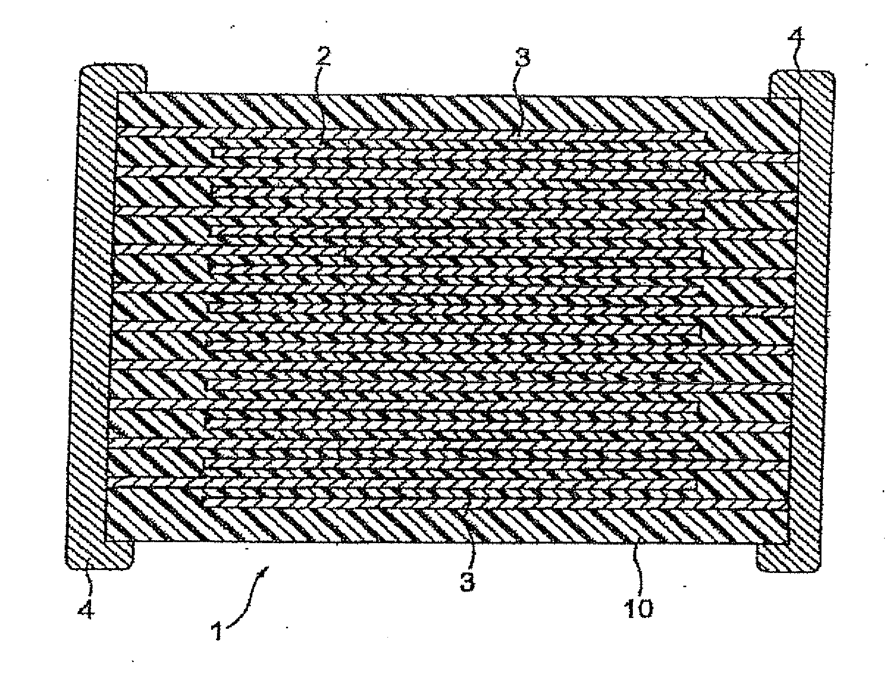
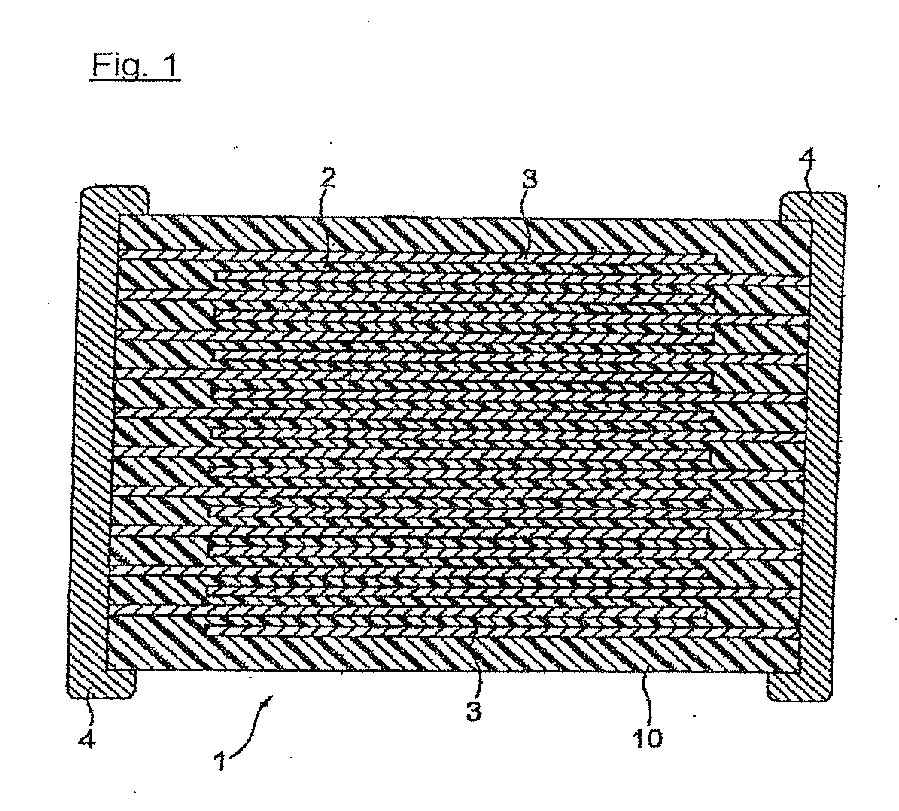
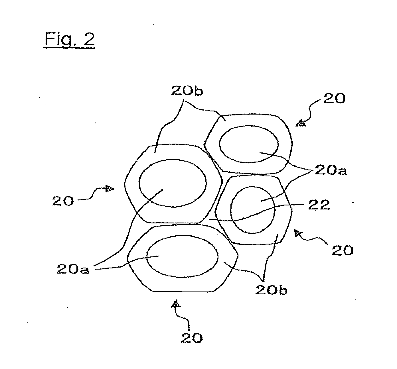
  • Dielectric ceramic composition and electronic component
  • Dielectric ceramic composition and electronic component
  • Dielectric ceramic composition and electronic component

Examples


Example

Example 1

[0086]Firstly, as for raw materials of a main component, BaTiO3 powder was prepared, and as for raw materials other than the main component, BaZrO3, Gd2O3, MgCO3, MnO and SiO2 were prepared respectively. Note that, the MgCO3 is included as MgO in the dielectric ceramic composition after firing.

[0087]Next, the prepared raw materials except for the main component were calcined at 1000° C. These calcined raw materials and the raw material of the main component were wet-mixed during 15 hrs by a ball-mill, after drying the dielectric material was obtained.

[0088]Note that, adding amounts of the respective subcomponents in terms of oxide or composite oxide were set as follows: adding amount of BaZrO3 is set as amounts shown in Table 1, adding amount of Gd2O3 is set as 5.0 mol, adding amount of MnO is set as 4.0 mol, adding amount of SiO2 is set as 2.8 mol and adding amount of MgO is set as 1.2 mol with respect to 100 mol of BaTiO3 which is a main component of the dielectric cerami...

Example

Example 2

[0104]Except for a temperature rising rate is set as a rate shown in Table 2, capacitor samples were made as similar with a sample No. 4 of the example 1, evaluation as similar with the example 1 was made. The results are shown in Table 2.

TABLE 2AvergeArea ofAbsoluteHighTemp.Temp.Concen-NonArea ofContentTemp.CharacteRisingtrationDiffusionDiffusionRatio ofSpecificLoadistic X7SampleRateof GdPhasePhaseGdPermit-Lifetimeat 125° C.No.[° C. / h]C[wt %]S1[%]S2[%]S2 × C[wt %]tivity[hr][%]*82007.030.070.04.988717−28.0 91807.028.072.05.088420−29.0101607.026.074.05.286229−30.0111407.024.076.05.384149−31.0 41007.022.078.05.582373−31.512807.020.080.05.680294−32.0*13 507.018.082.05.7789104−34.5*shows comparative examples of the present invention indicates data missing or illegible when filed

[0105]From Table 2, the area of diffusion phase can be controlled by controlling the temperature rising rate. As a result, the dielectric ceramic composition which improved reliability with maintaining ...

Example

Example 3

[0106]Except for changing the average concentration of the Gd by changing compositional amount of the Gd, capacitor samples were made as similar with the example 1, evaluation as similar with the example 1 was made. The results are shown in Table 3.

TABLE 3AvergeArea ofAbsoluteHighTemp,Temp.Concen-NanArea ofContentTemp.CharactRisingtrationDiffusionDiffusionRatio ofSpecificLoadistic XSampleRateBaZrO3of GdPhasePhaseGdPermit-Lifetimeat 125°No.[° C. / h][mol]C[wt %]S1[%]S2[%]S2 × C[wt %]tivity[hr][%]*1414011.07.430.070.05.286215−32.5*1514011.06.128.072.04.491122−34.0 1614011.06.728.072.04.889121−32.5 1714011.07.428.072.05.384720−29.0*1814011.08.228.072.05.979117−28.0*1914011.05.522.078.04.390782−34.0 2014011.06.122.078.04.889980−33.0 2114011.06.722.078.05.284576−32.0 2214011.07.422.078.05.881269−31.0*2314011.08.222.078.06.477567−30.0*2414011.05.520.080.04.4897107−34.5 2514011.06.120.080.04.9878105−33.0 2614011.06.720.080.05.485198−32.0*2714011.07.420.080.05.979495−31.0*2814011.07...


PUM

PropertyMeasurementUnit
Substance countaaaaaaaaaa

Abstract

A dielectric ceramic composition comprises a main component composed of at least one selected from BaTiO3, (Ba, Ca)TiO3, (Ba, Sr)TiO3 and (Ba, Ca, Sr)TiO3, an oxide of rare earth element and a composite compound including Ba. 9 to 13 mol of the composite compound in terms of composite compound is included in the dielectric composition. The dielectric ceramic composition includes surface diffusion particles having surface diffusion structure composed of non diffusion phase and diffusion phase including rare earth element. In the surface diffusion particle, when an area of the non diffusion phase is defined as S1, an area of the diffusion phase is defined as S2, S1 and S2 satisfy a relation of S1:S2=20:80 to 30:70 (Note that, except S1=30 and S2=70) , when an average concentration of the rare earth element in the surface diffusion particle is defined as C, S2 and C satisfy a relation of 4.8≦S2×C≦5.8. By the present invention, dielectric ceramic composition which improves reliability with obtaining good specific permittivity and temperature characteristic and electronic component to which the dielectric ceramic composition is applied can be obtained.

Description

BACKGROUND OF THE INVENTION[0001]1. Field of the Invention[0002]The present invention relates to a dielectric ceramic composition and an electronic component, more precisely relates to a dielectric ceramic composition which improves reliability with maintaining good specific permittivity and furthermore shows good temperature characteristics, and an electronic component to which said dielectric ceramic composition is applied.[0003]2. Description of the Related Art[0004]In recent years, there is a high demand for downsizing electronic components along with making progress in high density of electronic circuit. With a rapid progress in downsizing and increasing capacitance of a multilayer ceramic capacitor, applications are expanding, and there is various required properties.[0005]For example, for a mid-high voltage capacitor used for apparatus such as ECM (Engine Electric Computer Module), fuel injection device, electronic controlled throttle, inverter, convertor, HID headlamp unit, ...

Claims


Application Information

Patent Timeline
IPC IPC(8): H01G4/06C04B35/468
CPCC04B35/4682H01G4/30C04B35/638C04B2235/3203C04B2235/3206C04B2235/3208C04B2235/3213C04B2235/3217C04B2235/3224C04B2235/3241C04B2235/3248C04B2235/3262C04B2235/3272C04B2235/3277C04B2235/3287C04B2235/3409C04B2235/3418C04B2235/6562C04B2235/6582C04B2235/6584C04B2235/6588C04B2235/663C04B2235/80C04B2235/96H01G4/1227C04B35/6342
Inventor TAMURA, MASAYUKITAKAGI, SATOSHISAKURAI, DANAMAN, SANSHIROKAMADA, YUKI
Owner TDK CORPARATION
Why Eureka
Eureka Blog
Learn More