Switch Mode Converter and a Method of Starting a Switch Mode Converter

a converter and switch mode technology, applied in the direction of dc-dc conversion, power conversion systems, climate sustainability, etc., can solve the problems of damage to the attached device, the inability of the mosfet to send current in both directions, etc., to reduce and achieve adequate performance. , the effect of reducing the required board area and the cos

Inactive Publication Date: 2011-07-07
OPTIS WIRELESS TECH LLC
View PDF14 Cites 6 Cited by
  • Summary
  • Abstract
  • Description
  • Claims
  • Application Information

AI Technical Summary

Benefits of technology

[0009]By applying this technique the synchronous mosfets used as rectification elements can be turned on directly, without any gradual ramp-up of the gate voltage. If the input and output voltage readings are accurate no transient will occur, nor will there be any oscillations between the internal inductive components and the output capacitors. With the inventive solution, a microprocessor implementation completely removes the need for analogue nets which delays the turn on of the synchronous mosfets, rapidly charges the reference or similar. The converter can also be configured to start up against voltages higher than the configured output volt...

Problems solved by technology

One drawback, during start-up, is the capability of a mosfet to send currents in both directions.
This is a problem if the output of the converter already is biased (a voltage exists on the...

Method used


Image

  • Switch Mode Converter and a Method of Starting a Switch Mode Converter
  • Switch Mode Converter and a Method of Starting a Switch Mode Converter
  • Switch Mode Converter and a Method of Starting a Switch Mode Converter

Examples


Embodiment Construction

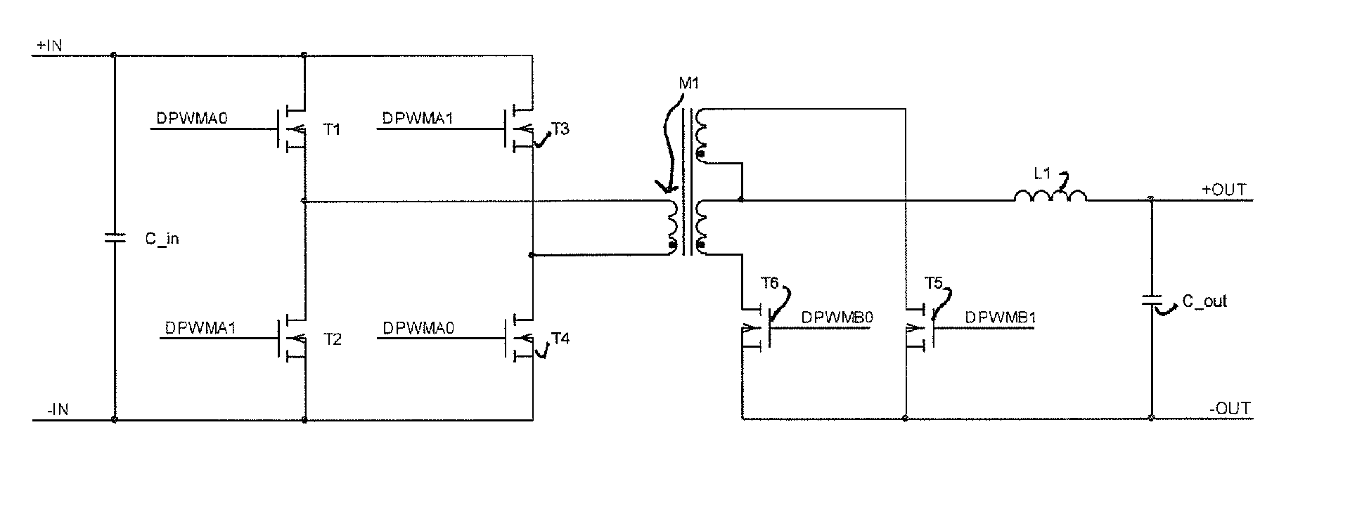
[0017]FIG. 1 illustrates a hard switched full bridge converter. The converter comprises a transformer M1 having a primary side including a primary winding and a secondary side including a secondary winding. On the primary winding a first and a second switch elements in the form of mosfets T1, T2 are interconnected by the drain of the second switch element T2 and the source of the first switch element T1. The interconnected source and drain are connected to one end of the primary winding. Third and fourth switch elements T3, T4 are interconnected by the drain of the fourth switch element T4 and the source of the third switch element and the interconnected source and drain are connected to the other end of the primary. The drains of the first T1 and third T3 switch elements are interconnected and the sources of the second T2 and fourth T4 switch elements are interconnected. Between the interconnected sources and the interconnected drains the input voltage is applied. The control signa...


PUM


Abstract

For a more stable start-up procedure, a switch mode power converter has at least one inductive component including an output inductor L1 and a synchronous rectification element, said power converter comprising a control device and being characterized in that the control device is arranged, at startup of the power converter, to determine a duty-cycle of the control signal, including a normal pulse width of the control pulse, and provide an initial control signal to the at least one switch element that is designed to balance the current in the at least one inductive component of the converter. The initial control signal preferably has a duration of 50% of the normal pulse width.

Description

TECHNICAL FIELD[0001]The present invention relates to a switch mode converter having direct energy transfer topology and a method of starting such a switch mode converter.BACKGROUND[0002]To increase the efficiency of switch mode converters the secondary side rectification element has gradually been changed from diodes to mosfets (synchronous rectification). This increases the efficiency of the converter and improves the dynamic performance. A mosfet used as a rectification element, where traditionally a diode would be used, is referred to as a synchronous mosfet. The mosfet is turned on when the diode was supposed to conduct. The use of a mosfet as a rectifying element reduces the losses significantly in high current applications.[0003]One drawback, during start-up, is the capability of a mosfet to send currents in both directions. This is a problem if the output of the converter already is biased (a voltage exists on the output) when the converter starts up. If this is not taken in...

Claims


Application Information

Patent Timeline
IPC IPC(8): H02M3/335
CPCH02M1/36Y02B70/1475H02M3/33592Y02B70/10
Inventor APPELBERG, MIKAEL
Owner OPTIS WIRELESS TECH LLC
Why Eureka
Try Eureka