
Protection for provider backbone bridge traffic engineering

Inactive Publication Date: 2011-07-07
RPX CLEARINGHOUSE
View PDF8 Cites 8 Cited by
  • Summary
  • Abstract
  • Description
  • Claims
  • Application Information

AI Technical Summary

Benefits of technology

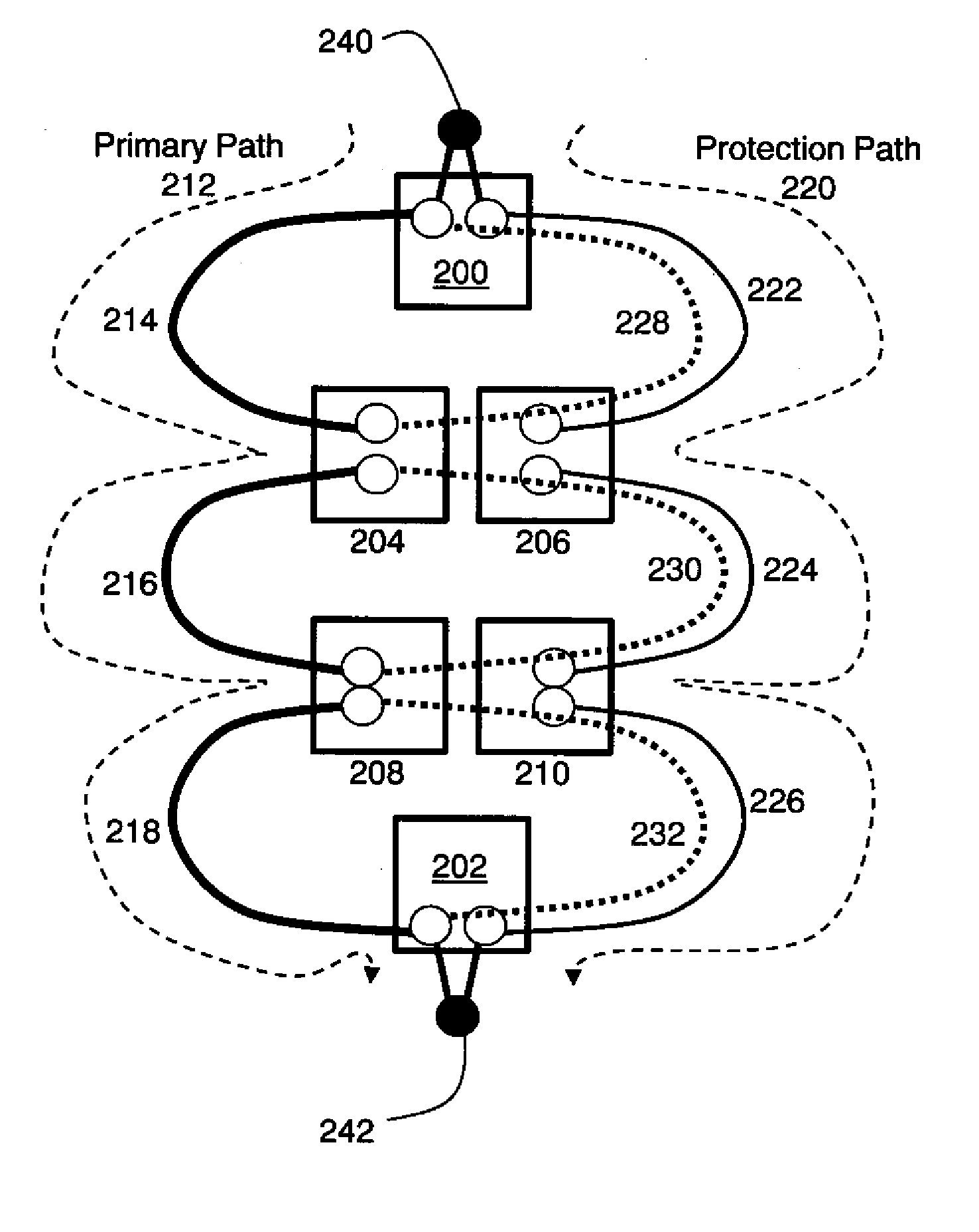
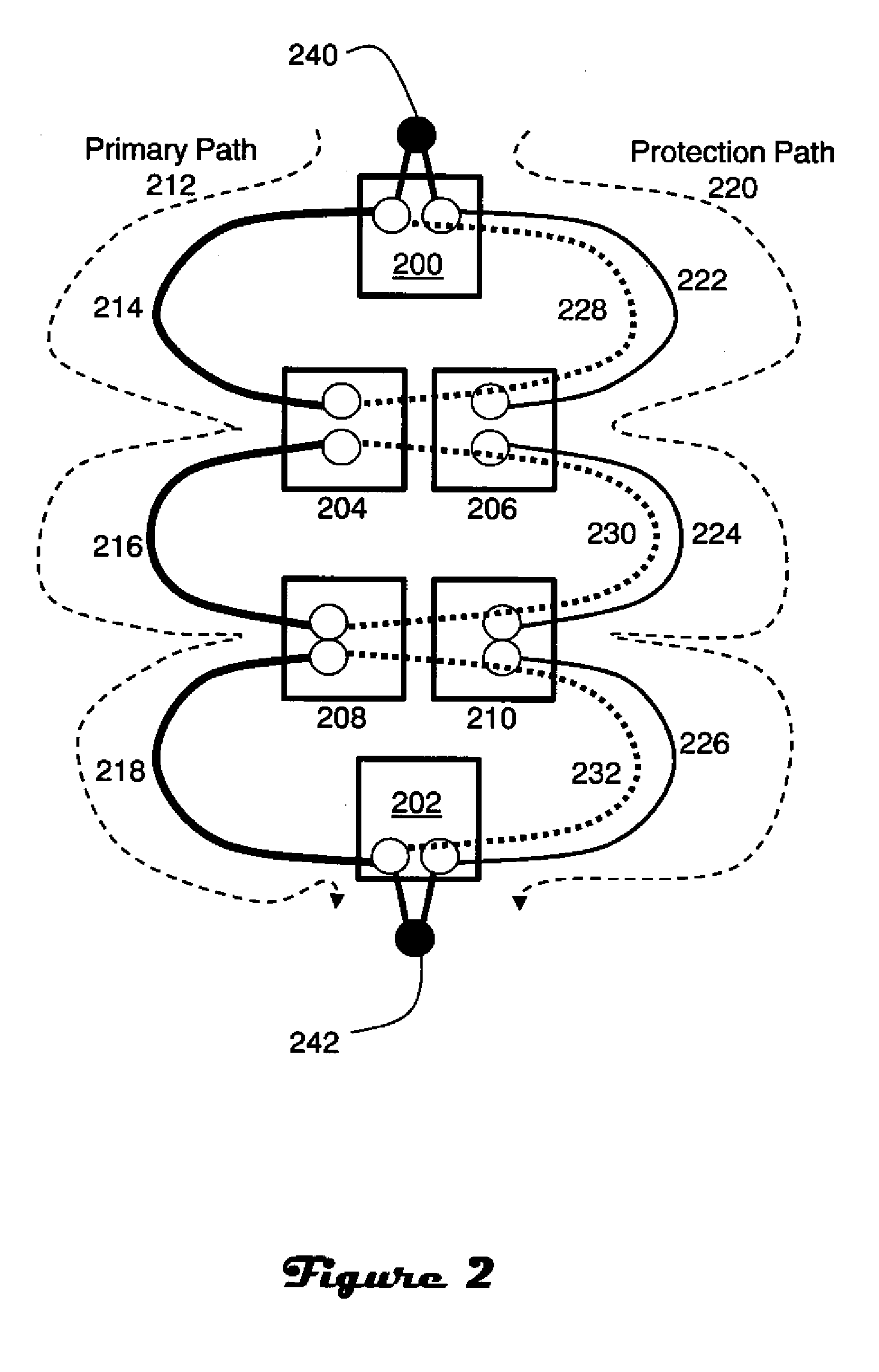
[0007]Advantages associated with the invention include more efficient use of network resources and enhanced protection. Although the multiplicity of paths required for comprehensive protection each require forwarding state to be installed in nodes to dictate the path to be taken by traffic, data traffic only travels on one end-to-end path at any time according to the 1:1 “head-end switching” model used by PBB-TE. This overcomes the inefficient use of network resources of previous 1+1 embodiments of section protection, which have also previously made uneconomic the deployment of section protection in combination with end-to-end path protection. Further, by utilizing section protection for the primary and protection end-to-end paths it is possible to tolerate one failure per ring, including the case of failure of one matched node (which faults two rings), while only doubling of the amount of state information stored at matched nodes. However, it should be understood that the invention is not limited to ring architectures.

Problems solved by technology

Although the end-to-end 1:1 protection paradigm works well, it has some drawbacks.
Further, in long distance communication deployments, the frequency of faults on the extended e2e path can become significant enough that probability of a second fault occurring on the protection path before a first fault is repaired becomes unacceptable.
Maintaining a large number of paths can be problematic because forwarding state is directly related to the number of paths installed, and every path adds a Continuity Fault Management (“CFM”) session to the terminating nodes.

Method used


Image

  • Protection for provider backbone bridge traffic engineering
  • Protection for provider backbone bridge traffic engineering
  • Protection for provider backbone bridge traffic engineering

Examples


Embodiment Construction

[0018]Data communication networks may include various computers, servers, nodes, routers, switches, bridges, hubs, proxies, and other network devices coupled to and configured to pass data to one another. These devices will be referred to herein as “nodes.” Data is communicated through the data communication network by passing protocol data units, such as Internet Protocol packets, Ethernet Frames, data cells, sections, or other logical associations of data, between the nodes by utilizing one or more communication links between the nodes. A particular protocol data unit may be handled by multiple nodes and cross multiple communication links as it travels between its source and its destination over the network.

[0019]The particulars described herein are for purposes of describing the illustrated embodiments of the present invention to provide what is believed to be a useful and readily understood description of principles and conceptual aspects of the invention. No attempt is made to ...


PUM


Abstract

Network protection between endpoints includes both end-to-end and local section protection. A primary path between the endpoints includes a plurality of links, and is protected on an end-to-end basis by a protection path associated with different links. At least one sections of the primary path is also protected on a local basis, where a “section” is a link, ring, trunk or other portion of a network. One or more sections of the protection path may also be protected on a local basis. In response to detection of a fault condition, section protection is utilized to overcome the fault if possible, and otherwise end-to-end protection is utilized. Invoking section protection does not imply a switchover from the primary end-to-end path to the protection end-to-end path. Rather, the primary end-to-end path is rerouted in the affected section.

Description

CROSS REFERENCE TO RELATED APPLICATIONS[0001]This application is a continuation of International Application Number PCT / US2009 / 048142, titled PROTECTION FOR PROVIDER BACKBONE BRIDGE TRAFFIC ENGINEERING, International Filing Date 22 Jun. 2009, which claims priority to U.S. Provisional Patent Application 60 / 096,011, filed 11 Sep. 2008.FIELD OF THE INVENTION[0002]This invention is generally related to network communications, and more particularly to protection for provider backbone bridge traffic engineering.BACKGROUND OF THE INVENTION[0003]Provider Backbone Bridge Traffic Engineering (“PBB-TE”) uses an end-to-end 1:1 protection paradigm, referred to in this document as “e2e protection”. This provides a robust protection mechanism which can be used across an arbitrary mesh of network connectivity. However, the underlying physical connectivity of many networks frequently uses rings of fiber, which makes protection over ring topologies an important scenario. In a network of cascaded ring...

Claims


Application Information

Patent Timeline
IPC IPC(8): H04L12/26H04L45/24H04L45/28
CPCH04L12/4625H04L41/0663H04L45/28H04L43/10H04L45/22H04L43/0817
Inventor BRAGG, NIGEL LAWRENCE
Owner RPX CLEARINGHOUSE
Learn More