
Operation and construction method of network using multi-rate interface panel

a technology of interface panel and construction method, which is applied in the direction of data switching network, electrical equipment, digital transmission, etc., can solve the problems of increasing the cost of facilities, poor maintenance of reserved lines, and difficulty in managing and cost of the whole network, so as to reduce the number of components, the effect of not increasing the circuit scale and reducing the number of components

Inactive Publication Date: 2011-07-07
TAMURA YUKIHISA +6
View PDF6 Cites 1 Cited by
  • Summary
  • Abstract
  • Description
  • Claims
  • Application Information

AI Technical Summary

Benefits of technology

"The present invention provides a method for managing a network using an interface panel that is compatible with a multi-rate. This means that the network can use different signals and have a more flexible and cost-effective management. The interface panel uses a programmable logic circuit that can be reconfigured, reducing the need for multiple components. The panel can also change the type of signal being processed, making it easier to replace the panel when needed. The invention also allows for easy management of reserved lines and quick recovery from failures. Overall, the invention provides a more efficient and economical way to manage optical fiber networks."

Problems solved by technology

However, since a conventional interface panel has a fixed rate, the whole network has a difficulty in terms of management and cost.
If an already existing optical fiber network runs down, it is necessary to install a new network, resulting in an increase in cost of facilities and poor maintenance of reserved lines.

Method used


Image

  • Operation and construction method of network using multi-rate interface panel
  • Operation and construction method of network using multi-rate interface panel
  • Operation and construction method of network using multi-rate interface panel

Examples


first embodiment

In the first embodiment, description will be made on a network configuration applying a multi-rate compatible transponder panel to an interface function unit. FIG. 6 shows the detailed structure of the interface function unit. In this structure, all of the interface panels (21-1 to 21-n) having a fixed rate are replaced with multi-rate compatible transponder panels (23-1 to 23-n). An upper level controller (50) sends a configuration start signal to the multi-rate compatible transponder panels (23-1 to 23-n). Upon reception of the configuration start signal, the multi-rate compatible transponder panels (23-1 to 23-n) realize configuration described with reference to FIG. 5.

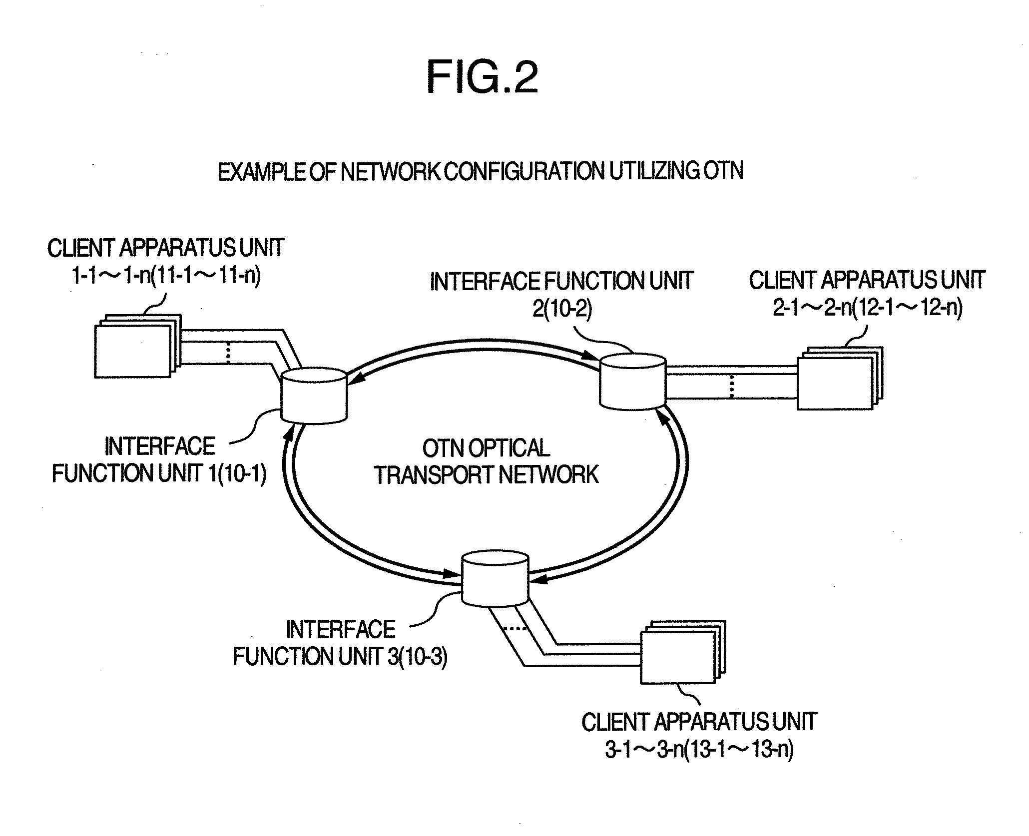
FIG. 7 shows by way of example a section between the client apparatus units 1-1 to 1-n (11-1 to 11-n) and client apparatus units 2-1 to 2-n (12-1 to 12-n) shown in FIG. 2, in an embodiment wherein multi-rate compatible transponder panels are applied to an actual network. FIG. 8 illustrates a pass setting procedure ...

second embodiment

In the second embodiment, description will be made on a method of configuring a reserved line adopting a multi-rate compatible regenerative repeater panel. FIG. 10 shows the detailed structure of the interface function unit adopting multi-rate regenerative repeater panels, in which all the regenerative repeater panels (22-1 to 22-n) of the FEC function unit (20) shown in FIG. 4 are replaced with multi-rate compatible regenerative repeater panels (25-1 to 25-n). The upper level controller (50) sends a configuration state signal to the multi-rate compatible repeater panels to conduct configuration described with reference to FIG. 5.

FIG. 11 shows an embodiment applying a multi-rate compatible regenerative repeater panel to an actual network, in which a 3R regenerative repeater unit is disposed in a section between the client apparatus units 1-1 to 1-n (11-1 to 11-n) and client apparatus units 2-1 to 2-n (12-1 to 12-n) shown in FIG. 2, by way of example. One reserved line is provided in...


PUM


Abstract

An interface unit for processing a first signal and a second signal, the second signal set to different transmission rate from the first signal and / or a different signal type from the first signal, including a plurality of interface panels, each of the plurality of interface panels including: a storage device which stores a first logic circuit data corresponding to the first signal and a second logic circuit data corresponding to the second signal, a configuration function unit which controls to select the first logic circuit data or the second logic circuit data, and a programmable logic circuit which reconfigures the first logic circuit data or the second logic circuit data based on a selection by the configuration function unit.

Description

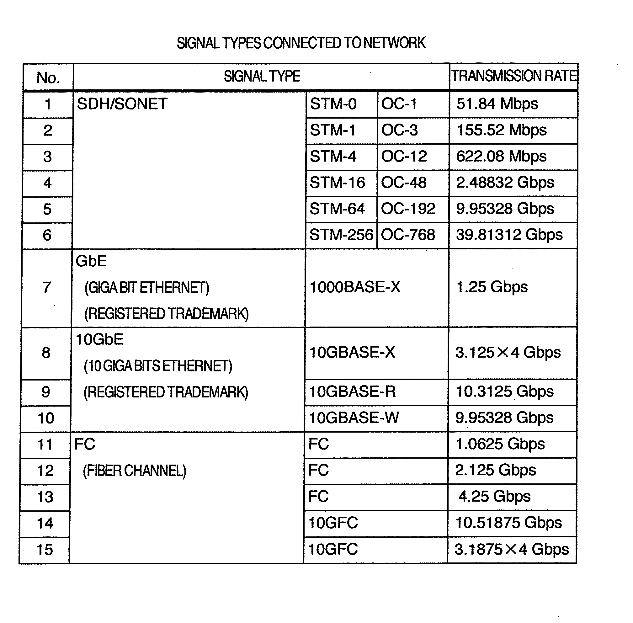
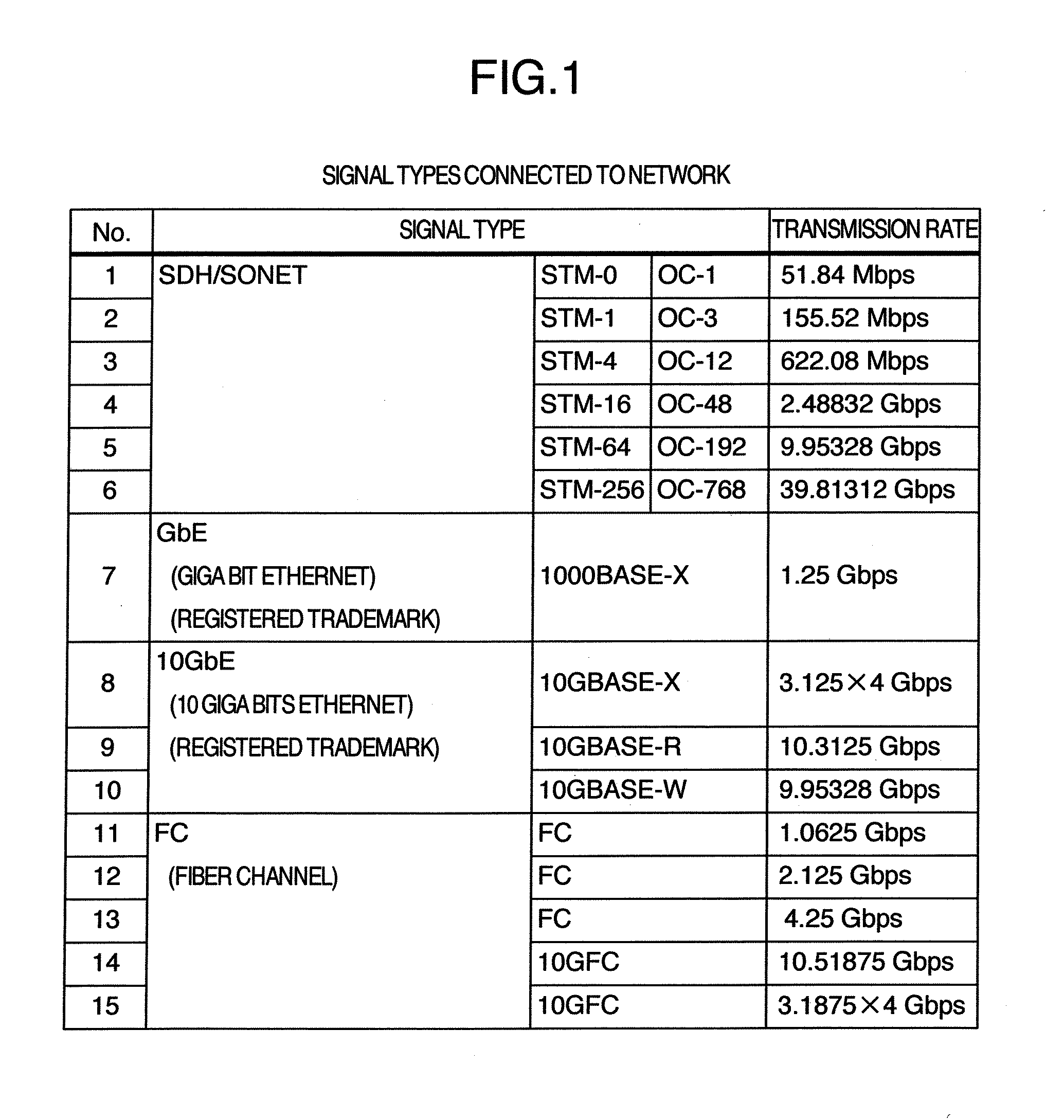
INCORPORATION BY REFERENCEThe present application claims priority from Japanese applications JP-2007-064339 filed on Mar. 14, 2007 and JP-2007-096007 filed on Apr. 2, 2007 the contents of which are hereby incorporated by reference into this application.BACKGROUND OF THE INVENTIONThe present invention relates to a network having excellent operability using interface panels capable of processing a variety of signal types in a network handling a number of signal types, and to a method of configuring a network capable of flexible handling of service addition / change and system failure.High speed and large capacity of a network typically the Internet have been required because of an increase in traffics. To solve this, an optical network typically representing a Wavelength Division Multiplexing (WDM) scheme has prevailed rapidly. WDM is a scheme for multiplexing optical signals having different wavelengths in a single optical fiber, and can realize large capacity communications easily by ...

Claims


Application Information

Patent Timeline
Patent Type & Authority Applications(United States)
IPC IPC(8): H04L12/66
CPCH04J3/047H04J3/1664H04L49/602H04J2203/0046H04J3/167
Inventor TAMURA, YUKIHISAMAKINO, MANABUTAKATORI, KOJIMURAKAMI, HIROMIKUSANO, YOSHIMASAATSUMI, TOSHIYUKISHIBASAKI, MASATOSHI
Owner TAMURA YUKIHISA
Learn More