Cutting unit for a thermoforming machine or press and a thermoforming machine equipped with such cutting unit

a cutting unit and thermoforming machine technology, which is applied in the field of cutting units for thermoforming machines or presses as well as thermoforming machines equipped with such units, can solve the problems of affecting the quality of finished thermoforming products, difficult restoration of respective molds, and high cost. , to achieve the effect of high quality

Active Publication Date: 2011-07-07
OMV MACHINERY
View PDF34 Cites 10 Cited by
  • Summary
  • Abstract
  • Description
  • Claims
  • Application Information

AI Technical Summary

Benefits of technology

[0007]The main object of the present invention is therefore to provide an in-mold cutting unit for a thermoforming (press) machine which is versatile and which allows

Problems solved by technology

In practice, a small enlargement integral with the object always remains at the position of each witness, which is detected by the user of the object at the time of use—both via touch and sight, and constitutes a visible and tactile defect of the thermoformed product, a defect which negatively affects the quality of the finished therm

Method used


Image

  • Cutting unit for a thermoforming machine or press and a thermoforming machine equipped with such cutting unit
  • Cutting unit for a thermoforming machine or press and a thermoforming machine equipped with such cutting unit
  • Cutting unit for a thermoforming machine or press and a thermoforming machine equipped with such cutting unit

Examples


Embodiment Construction

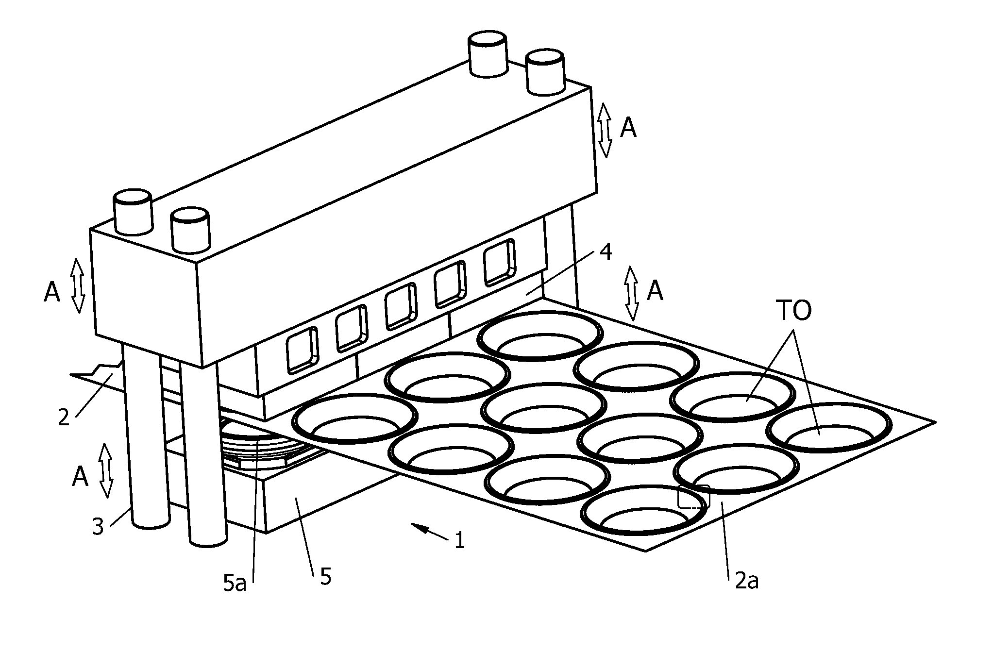
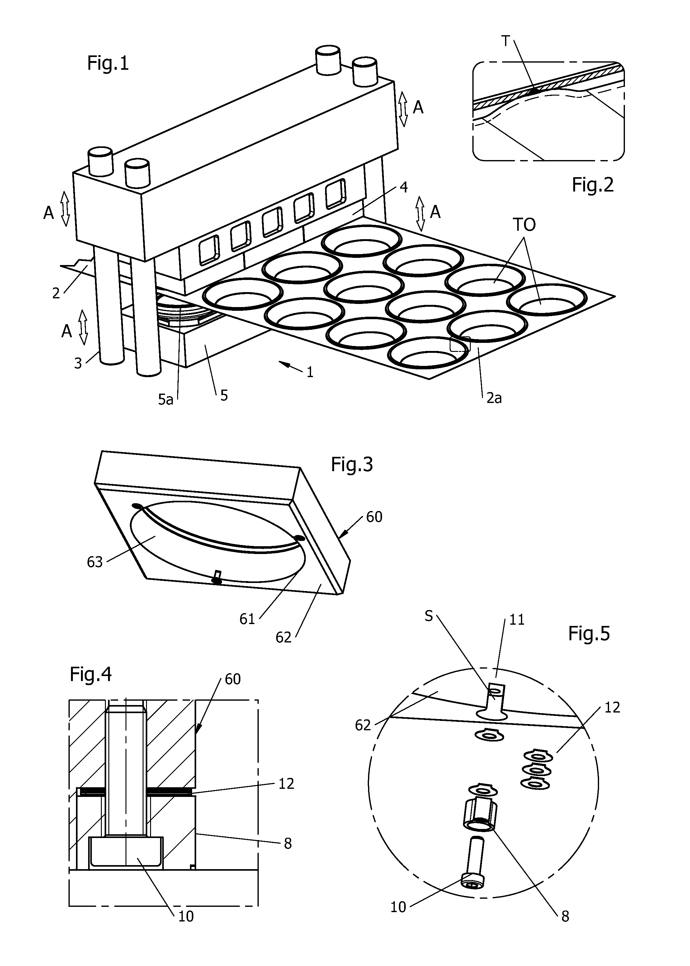
[0037]First, with reference to FIGS. 1 to 12, a thermoforming and in-mold cutting machine 1 according to the present invention is illustrated, having, as is known in the state of the art, a support framework generically indicated with 3, a (e.g. upper) male mold element 4, and a (e.g. lower) countermold element or female mold 5, supported by the framework 3. One or both male 4 and female 5 molds are slidably mounted on the framework 3 so that they can be brought close to each other / far from each other in use (arrows A in FIG. 1). For such purpose, suitable drive means are provided for, as it is known in the state of the art, such as a motor-toggle group, suitable for imparting a mutual approaching / moving away from motion.

[0038]The countermold element 5 delimits one or more thermoforming cavities 5a, whereas the male mold 4 can be equipped with many pad elements (not illustrated in the drawings), at least equal to the number of thermoforming cavities 5a with which they are intended t...


PUM

PropertyMeasurementUnit
Widthaaaaaaaaaa

Abstract

The present disclosure relates to an in-mold cutting unit for a thermoforming machine having at least one mold element (4), at least one counter-mold element (5) intended to cooperate, in use, with a respective mold element (4), and actuation means intended to command the relative movement of the mold (4) and countermold (5) elements; the cutting unit comprising at least one annular knife element (60) having a sharp edge (61), and at least one counter-cutting element (7) for each knife element (60), defining a sharp counter-edge portion (71), and the in-mold cutting unit comprising at least one witness-forming insert (8) removably housable in a respective reception seat (S) at the at least one annular knife element (60) or the at least one counter-cutting element (7), and delimiting at least one recess or incision (89) thereon, during use very close to the sharp edge (61) of the annular knife element (60) or to the sharp counter-edge portion (71) for the formation of a respective witness (T) between a thermoformed object (TO) and residual web (2a).

Description

FIELD OF INVENTION[0001]The present invention refers to a cutting unit for a thermoforming machine or press as well as a machine equipped with such unit.BACKGROUND OF INVENTION[0002]Thermoformed objects are generally produced from a continuous sheet of thermoformable material that after having been suitably laminated is fed while being still hot between mold and the countermold of a thermoforming machine, and is then thermoformed by bringing the mold and countermold in abutment against each other. One or more thermoformed objects are thus obtained, while the remaining material of the sheet, termed “residual web” in jargon, is removed and suitably recycled.[0003]The thermoformed object or objects thus obtained are extracted from the thermoforming mold by means of a suitable extractor device, or as provided for according to the present invention, they are extracted by the residual web itself, to which they remain anchored at thin cords or “witnesses”; from which they will subsequently...

Claims


Application Information

Patent Timeline
IPC IPC(8): B28B11/12B23P6/00
CPCB26F2001/4481B29C51/32B26F2001/4427B26F1/44B29C2793/0036Y10T29/49726B29L2031/7132
Inventor BISSOLI, GIANCARLO
Owner OMV MACHINERY
Why Eureka
Try Eureka