Spine stabilization system and method

a spine and system technology, applied in the field of orthopaedics, can solve the problems of spinal canal stenosis, post-surgery kyphosis, compression and damage of spinal cord and nerve roots, etc., and achieve the effect of controlling the tension of the system

Active Publication Date: 2011-07-07
DEPUY SYNTHES PROD INC
View PDF8 Cites 7 Cited by
  • Summary
  • Abstract
  • Description
  • Claims
  • Application Information

AI Technical Summary

Benefits of technology

[0011]The spine stabilization system in yet a different embodiment may include an elastic, stretchable cord having a first end region and a second end region, a first hook member fixedly attached to the elastic cord, and a second hook member attached to the elastic cord, the second hook member being adjustably positionable along the length of the elastic cord, wherein the elastic cord and pair of hook members are preassembled and the second hook member is adjustably positionable along the length of the elastic cord to adjust the effective length of the elastic cord to control the tension of the system.
[0012]The second hook member may be fixedly securable to the elastic cord in situ by one of the group consisting of crimping, bonding, welding, clamping, gluing, press fitting and the use of set screws. The stabilization system may further include a securing mechanism for securing the hook members to the elastic cord. The securing mechanism may comprise a blocking cap for preventing at least one of the hook members from sliding off of the elastic cord and the blocking cap may be attached at a predetermined and fixed position on the elastic cord. The stabilization system may further comprise a securing mechanism for adjustably securing the hook member to the elastic cord so that the position of the hook member on the elastic cord can be changed during the procedure. The stabilization system may include a plurality of preassembled cord and hook members.
[0013]The present invention is also directed to a method of stabilizing the spine including providing a spine stabilizing system having an elongated member with a first end region and a second end region, a pair of hook members for attaching to the lamina of a vertebra, wherein the first hook member is attached to the first end region and a second hook member is attached to the elongated member. The method also includes the steps of securing a first hook member to a first lamina of a first vertebra, passing the elongated member beneath the spinous process of a second vertebra, and securing the second hook member to a second lamina of the first vertebra. The method may further include stretching the elongated member to provide tension to the hook members. The method may further include the step of adjusting the effective length of the elongated member. The step of adjusting the effective length of the elongated member may be performed after the hooks are secured to the vertebra. Adjusting the effective length of the elongated member may include adjusting the position of the hook member along the length of the elongated member.
[0014]In a different embodiment, the method of stabilizing the spine may include the step of providing a spine stabilization system having an elongated member with a first end region and a second end region, and a pair of attachment mechanisms for attaching to vertebra. The first attachment mechanism is attached to the first end region and a second attachment mechanism is attached to the second end region. The method may further include the steps of securing a first attachment mechanism to a first vertebra, securing a second attachment mechanism to a second vertebra and placing tension on the first and second attachment mechanisms. The method may further include the step of stretching the elongated members to provide tension to the attachment mechanisms. The attachment mechanisms are preferably hooks and the method may further include attaching the first hook to a first lamina and a second hook to a second lamina. The method may further include the step of adjusting the effective length of the elongated member. The step of adjusting the effective length of the elongated member may be performed after the second attachment mechanism is attached to the second vertebra.

Problems solved by technology

This narrowing of the spinal canal referred to as spinal stenosis can compress and damage the spinal cord and nerve roots.
Performance of a cervical laminectomy or laminoplasty often results in a resection or disruption of the ligamentum nuchae, which may lead to post-surgery kyphosis.

Method used


Image

  • Spine stabilization system and method
  • Spine stabilization system and method
  • Spine stabilization system and method

Examples


Embodiment Construction

[0025]Certain terminology is used in the following description for convenience only and is not limiting. The words “right”, “left”, “lower”, “upper”, “above”, “below”, “top” and “bottom” designate directions in the drawings to which reference is made. The words “inwardly” or “distally” and “outwardly” or “proximally” refer to directions toward and away from, respectively, the geometric center of the spine stabilization assembly and related parts thereof. The words, “anterior”, “posterior”, “superior,”“inferior”, “medial” and “lateral” and related words and / or phrases designate preferred positions and orientations in the human body to which reference is made and are not meant to be limiting. The terminology includes the above-listed words, derivatives thereof and words of similar import.

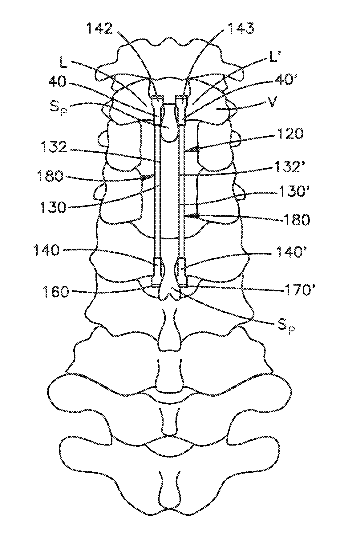
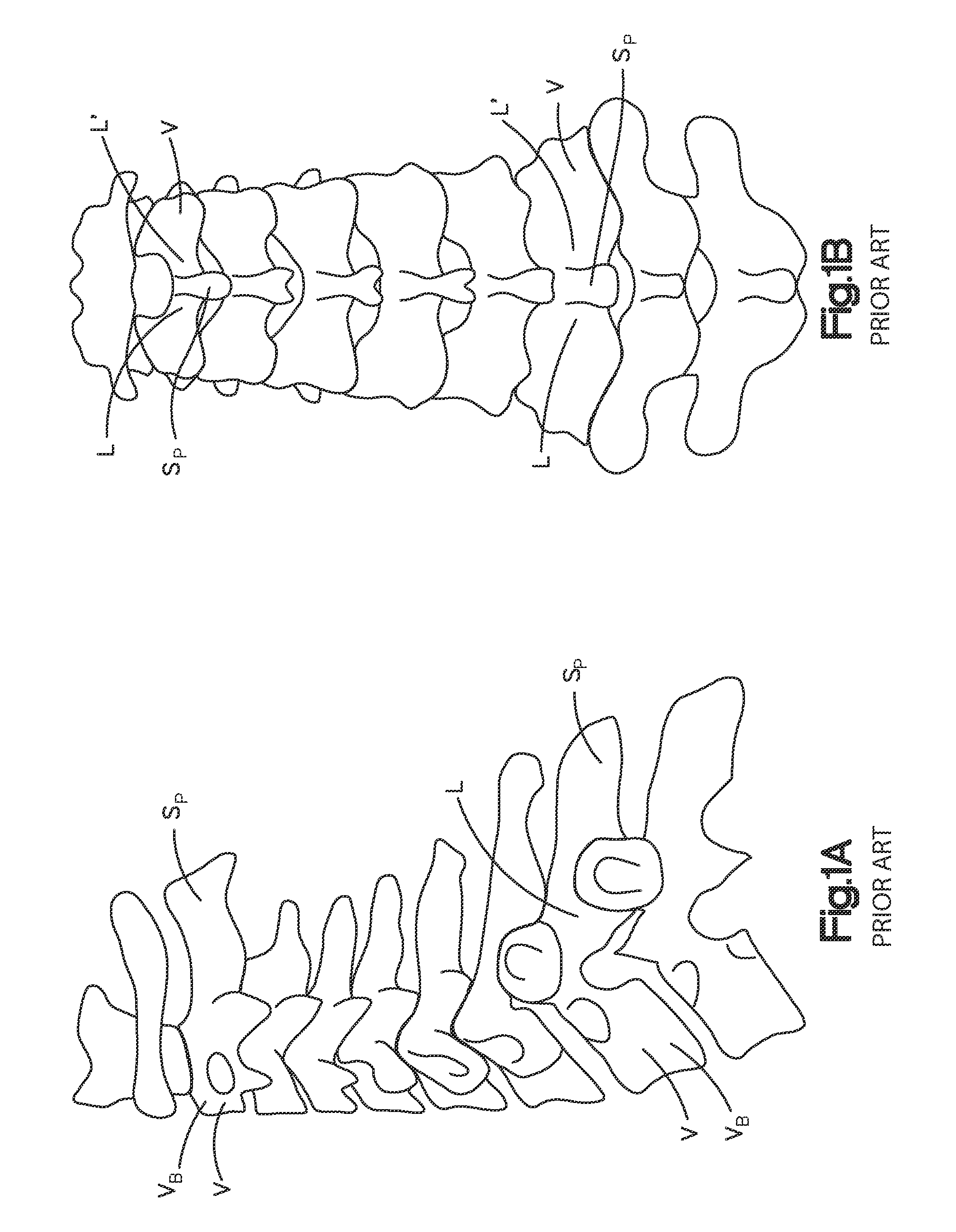
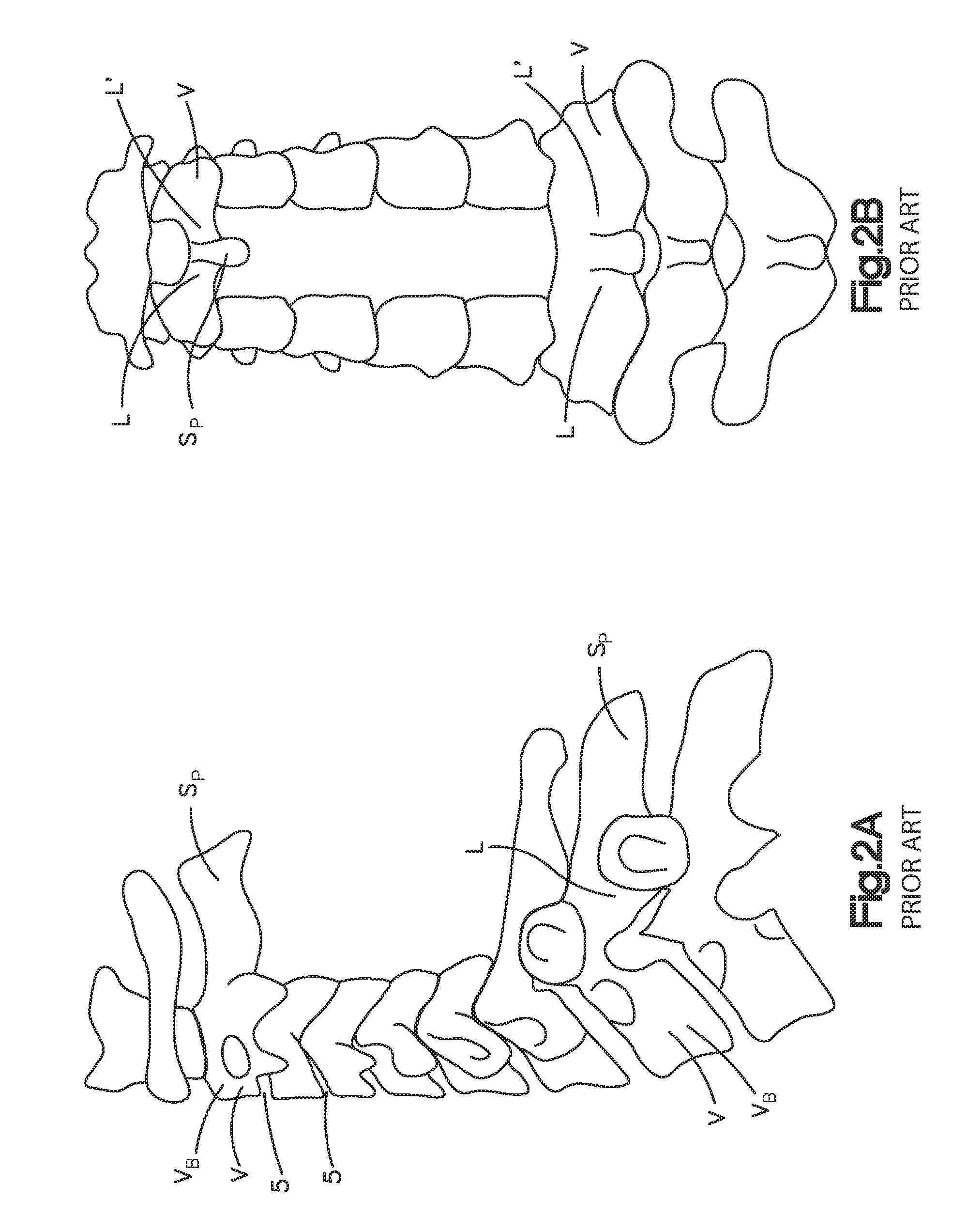
[0026]FIGS. 1A-B illustrate the cervical and portions of the thoracic region of a spine having vertebra V. Each vertebra V includes a vertebral body VB, spinous process Sp, and two lamina L, L′, a fir...


PUM


Abstract

A stabilization system for the spine that includes an elongated member, preferably an elastic cord, and a plurality of attachment mechanisms, preferably lamina hooks. The stabilization system is configured to extend across a plurality of spinal motion segments to dynamically couple the motion segments in a manner that places the system in tension to apply a compression force to the posterior of the spine. The system and method may have particular application after a laminectomy or laminoplasty procedure.

Description

CROSS REFERENCE TO RELATED APPLICATION[0001]This application claims the benefit of U.S. Provisional Application No. 61 / 099,019 filed Sep. 22, 2008, entitled “STABILIZATION SYSTEM AND METHOD”, the contents of which is incorporated in its entirety by reference herein.FIELD OF THE INVENTION[0002]The present invention relates generally to orthopedics. More specifically, a preferred embodiment of the present invention relates to a system and method for stabilization of a spine.BACKGROUND OF THE INVENTION[0003]The spinal canal can be narrowed by the formation of bone spurs arising from the back of the vertebral body or the ligament behind the vertebral bodies. This narrowing of the spinal canal referred to as spinal stenosis can compress and damage the spinal cord and nerve roots. It is desirable to relieve this pressure in and to the spinal cord. Laminectomy, laminotomy or laminoplasty procedures are procedures to relieve pain from spinal stenosis by creating more space for the spinal co...

Claims


Application Information

Patent Timeline
Patent Type & Authority Applications(United States)
IPC IPC(8): A61B17/70A61B17/88
CPCA61B17/7046A61B17/7022
Inventor CAIN, CHRISTOPHER MARDEN JOHN
Owner DEPUY SYNTHES PROD INC
Why Eureka
Try Eureka