Method and apparatus for transmitting or receiving information between a down-hole eqipment and surface

a technology of transmitting or receiving information and down-hole eqipment, which is applied in the direction of surveying, instruments, and wellbore/well accessories, can solve the problems of increasing the cost of the well, and increasing the reliability of such systems, so as to improve the efficiency of the receiving and/or transmitting method, the effect of increasing the signal to noise ratio

Inactive Publication Date: 2011-07-14
SCHLUMBERGER TECH CORP
View PDF13 Cites 47 Cited by
  • Summary
  • Abstract
  • Description
  • Claims
  • Application Information

AI Technical Summary

Benefits of technology

[0009]In another embodiment, the well further comprises a relay transducer, said relay transducer located at a third location and comprising two electrodes, which are first and second well electrodes, said first and second well electrodes being substantially in electrical contact with the casing; and the method further comprising the step of: (i) receiving the electric signal with the third transducer by detecting said signal between the first and second well electrodes; and (ii) transmitting the electric signal with the third transducer by applying said signal between the first and second well electrodes. The well can further comprising a plurality of additional relay transducers. The advantages of using relays are to increase the range of the communication and / or to communicate with various locations in the well. At least, the first and second well electrodes have respectively a first well electrical resistance and a second well electrical resistance when in contact with the casing which should be as lowest as possible. Because, of presence of non conductive mud within the casing or non conductive material on the casing, the resistance is not null. Preferably, the first well electrical resistance and / or the second well electrical resistance is / are below one thousand Ohms; more preferably, below one hundred Ohms; most preferably, ten Ohms.
[0011]Preferably, the well comprises a tubing and at least one of the electrodes taken in the list: first downstream electrode, second downstream electrode, first upstream electrode, second upstream electrode, first well electrode, second well electrode, electrodes from the other transducers, is insulated electrically from the tubing, preferably also, is further insulated electrically from other conductive elements in the well and preferably also, is further shielded electromagnetically. The insulation allows controlling the injected current between electrodes independently of the potential of the tubing or of the other conductive elements. The effects of the electrical insulation of the electrode are clearly tangible and useful for the better efficiency of the receiving and / or transmitting method. The electrical insulation increases the signal to noise ratio. The shielding avoids and protects against electrical interferences coming from the well.
[0017]In another embodiment, the apparatus further comprises at least another third transducer, said third transducer located at a third location and comprising two electrodes, which are first and second well electrodes, said first and second well electrodes being substantially in electrical contact with the casing. The third transducer can be a relay transducer. The advantages of using relays are to increase the range of the communication and / or to communicate with various locations in the well. At least, the first and second well electrodes have respectively a first well electrical resistance and a second well electrical resistance when in contact with the casing which should be as lowest as possible. Because, of presence of non conductive mud within the casing or non conductive material on the casing, the resistance is not null. Preferably, the first well electrical resistance and / or the second well electrical resistance is / are below one thousand Ohms; more preferably, below one hundred Ohms; most preferably, ten Ohms.
[0019]Preferably, the well comprises a tubing and at least one of the electrodes taken in the list: first downstream electrode, second downstream electrode, first upstream electrode, second upstream electrode, first well electrode and second well electrode, is insulated electrically from the tubing, preferably also, is further insulated electrically from other conductive elements in the well and preferably also, is further shielded electromagnetically. The insulation allows controlling the injected current between electrodes independently of the potential of the tubing or of the other conductive elements. The effects of the electrical insulation of the electrode are clearly tangible and useful for the better efficiency of the receiving and / or transmitting method. The electrical insulation increases the signal to noise ratio. The shielding avoids and protects against electrical interferences coming from the well.

Problems solved by technology

Safely and accurately placing the cables within the well bore along side of the piping structure or string is difficult and time consuming to achieve.
In addition, this requires additional equipment to be used increasing the costs associated with the well.
Well bores are a harsh environment, and numerous failure mechanisms exist that cause the reliability of such systems to be unacceptably low.
Furthermore, a cable incorporating such sensors, or being connected to control devices, located at a substantial depth cannot be lowered in every situation.
The installation of such cable is possible when completing the well, but become practically impossible when the well is completed.
In particular, the cable may not be able to be lowered when valves or separation devices cannot be crossed by a cable, whether or not the cable is fitted with sensors.
For example, if the resistivity of certain layers is inadequate, as is the case with certain sedimentary, tertiary, pericontinental rocks like those of the North Sea or the Gulf of Mexico, the attenuation can become excessive along the well, which makes it impossible to use such a device in most offshore wells unless it is possible to accept a drastic reduction in the transmitted information flow.

Method used


Image

  • Method and apparatus for transmitting or receiving information between a down-hole eqipment and surface
  • Method and apparatus for transmitting or receiving information between a down-hole eqipment and surface
  • Method and apparatus for transmitting or receiving information between a down-hole eqipment and surface

Examples


Embodiment Construction

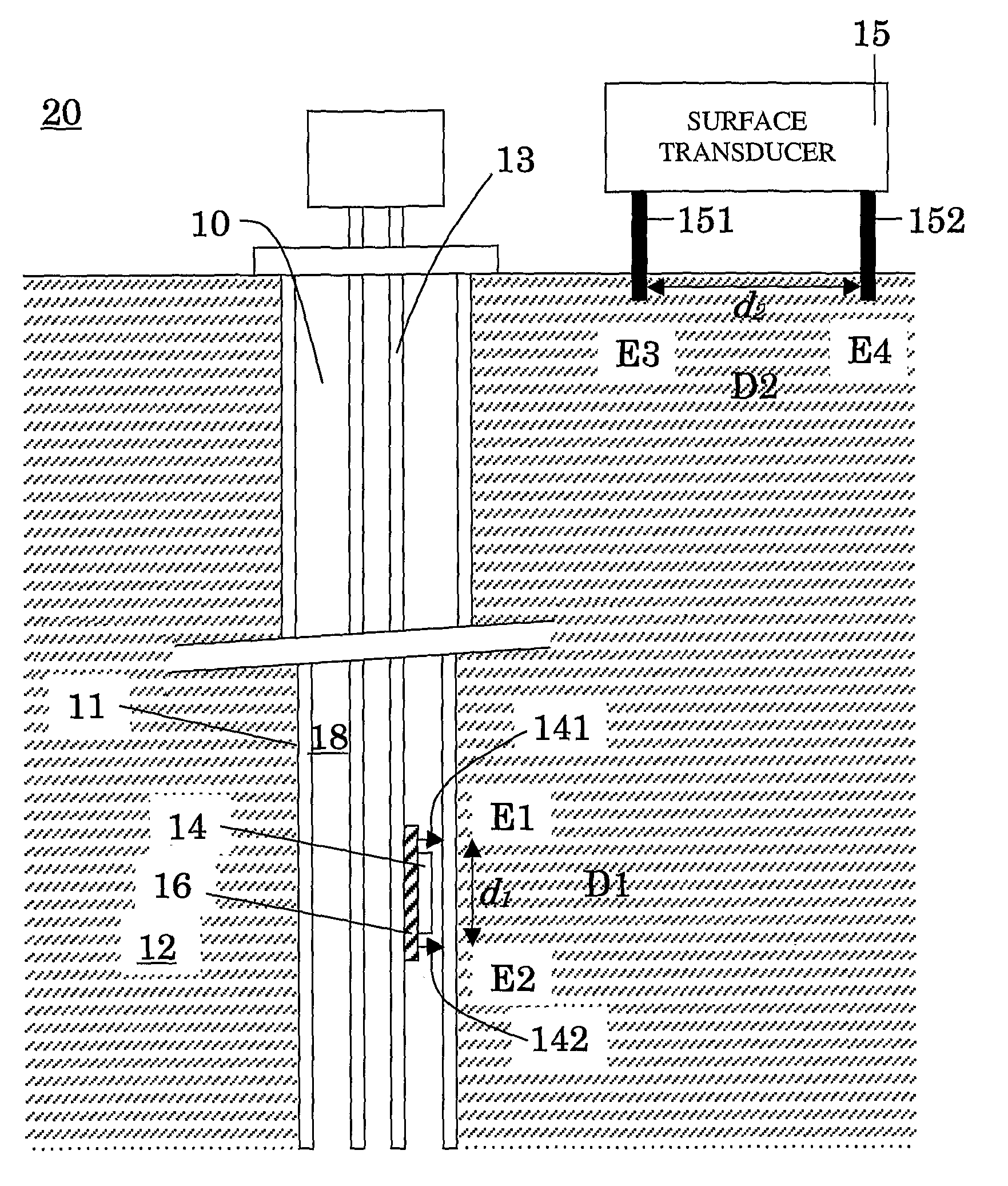
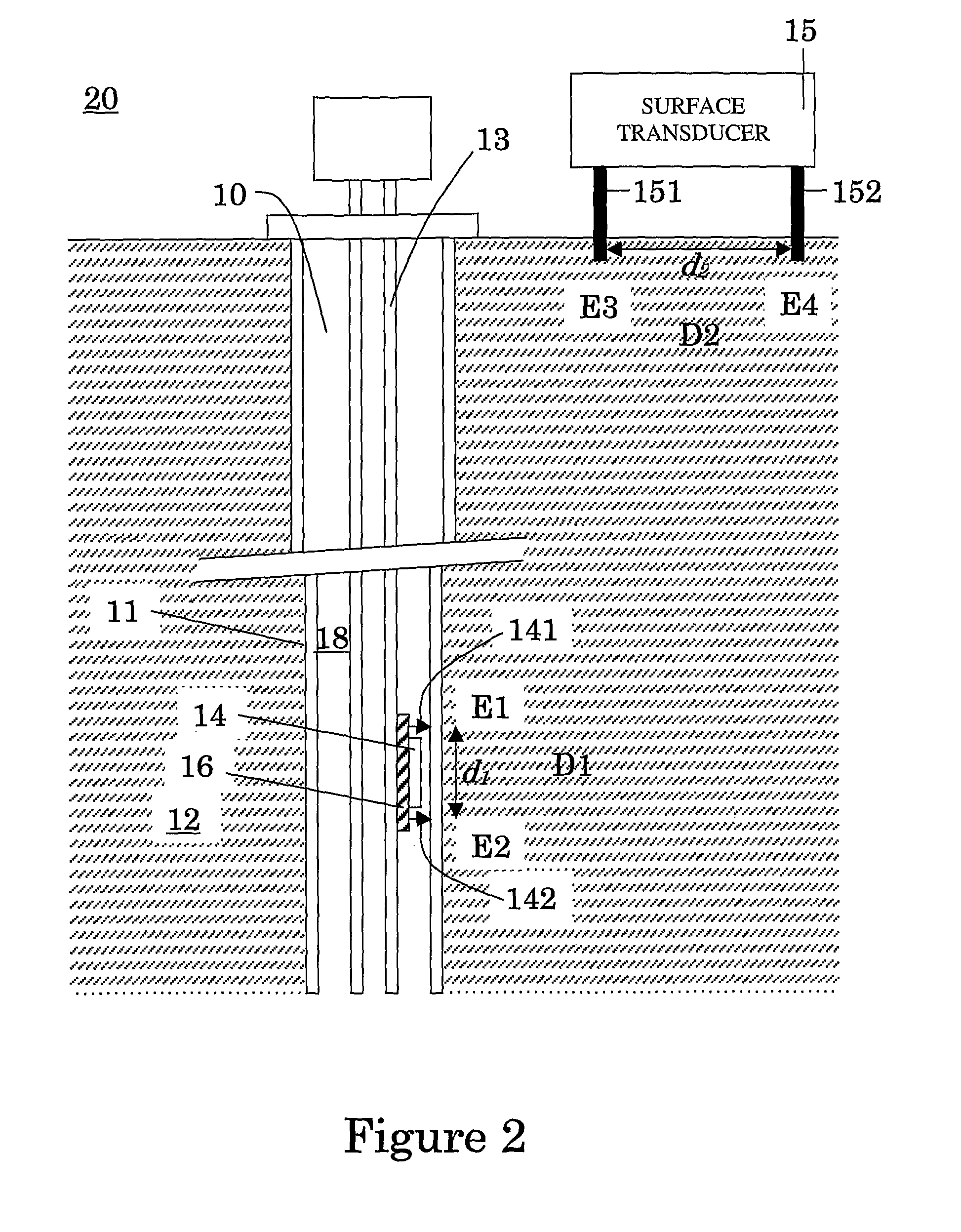
[0056]FIG. 2 is an illustration of the apparatus according to the present invention in a first embodiment. A first transducer 14, the well transducer, is installed in a well 10, the well comprising a tubing 13 and a casing 11 surrounding formation 12. An annular 18 is formed between the casing and the tubing, which is filled with an annular fluid. The casing and the tubing are conductive, normally made of steel. The well transducer has an upper electrode 141 which ensures contact with the casing at a pole E1 and an upon electrode 142 which also ensures contact with the casing at a pole E2. Preferably, the upper electrode 141 and / or the upon electrode 142 are / is insulated electrically from the tubing 13 with an insulator 16. Additionally, the upper electrode 141 and / or the upon electrode 142 are / is insulated against other conductive elements in the well, such as highly conductive annular fluids. The insulation allows to control the injected current between the electrodes 141 and 142 ...


PUM


Abstract

The invention provides a method of receiving and / or transmitting information in a well drilled in a geological formation between a first location and a second location, the well comprising a casing communicating with the geological formation. The method comprises placing a first transducer at a first location, placing a second transducer at a second location. Transmitting an electric signal between the first and second transducers.

Description

FIELD OF THE INVENTION[0001]The present invention broadly relates to wireless telemetry. More particularly the invention relates to an apparatus and related method for transmitting or receiving information between a downhole equipment connected to an underground tubing or casing and a surface device.DESCRIPTION OF THE PRIOR ART[0002]Oil and gas wells are expensive to construct, and it is advantageous to operate these wells as efficiently as possible. One way of providing for an increased efficiency in the operation of wells is to place equipment downhole in the well bore under the control of other equipment located on the surface. The equipment can be measurement sensors which supply useful information for the subsequent working of the well, for example data regarding pressure, the nature of the solids and fluids encountered, the temperature, etc. The equipment can be other controllable or monitoring equipments which supply important orders from the surface to control various parame...

Claims


Application Information

Patent Timeline
Patent Type & Authority Applications(United States)
IPC IPC(8): E21B49/00E21B47/12G01V3/34H04H60/31
CPCE21B47/12G01V11/002E21B47/122E21B47/13G01V11/005G01V3/083
Inventor LEMENAGER, ERWANLULING, MARTINMATHIEU, YVESCHOUZENOUX, CHRISTIAN
Owner SCHLUMBERGER TECH CORP
Why Eureka
Try Eureka