Temperature-compensated piezoelectric flexural transducer

a flexural transducer and temperature compensation technology, applied in mechanical equipment, generators/motors, valves, etc., can solve the problems of unfavorable use in valve arrays with low channel spacing, disadvantageous double overall width, and further disadvantageous fabrication of flexural transducer units

Active Publication Date: 2011-07-14
EXEL IND SA +1
View PDF7 Cites 13 Cited by
  • Summary
  • Abstract
  • Description
  • Claims
  • Application Information

AI Technical Summary

Benefits of technology

[0007]Due to the flow-capability of the power transmission fluid the fluid bearing is suited to compensate for slow position and geometry changes of flexural transducer and housing, without transferring significant flexural forces between the housing and transducer element. The fluid bearing thus effects a compensation of deformations or stresses of the piezo flexural transducer or other parts due to temperature change, forces, stress, aging and drift. In contrast to conventional flexural transducers, where such stresses or parasitic movements influence the actuation characteristics of the actuator, by incorporating a fluid bearing these can no more have an impact on the actuating mechanism. The fluid bearing according to the invention further spares elaborate efforts for temperature compensation and the need for precise assembly. Due to the fluid bearing also larger deformations of the housing can be accepted, which e.g. can appear within pressure loaded fluid valves. This allows altogether a space and material-saving design, particularly miniaturization.
[0010]According to an advantageous embodiment reaction forces or torques are transmitted from a surface of the transducer element via the viscous power transmitting fluid to a surface of the housing. In a further preferred variant the surface of the flexural transducer element is the surface of a substrate layer of the flexural transducer element. By utilizing surfaces of the flexural transducer element and of the housing as part of the fluid bearing the actuation device can be fabricated very easy and inexpensive. An exceptionally effective power transfer is given by a further suitable embodiment, in which the viscous power transmitting fluid is within a gap between the surface of the flexural transducer element and the surface of the housing. Finally, another embodiment is proposed, characterized in that the surface of the housing is an inner surface of an open oder closed cavity.

Problems solved by technology

Compared to conventional piezoelectric flexural elements the double overall width is however disadvantageous, which e.q. is unfavorable for use in valve arrays with low channel spacing.
The technically complex fabrication of the flexural transducer unit is further disadvantageous.
Also most delicate fabrication and assembly steps would have to be carried out.

Method used


Image

  • Temperature-compensated piezoelectric flexural transducer
  • Temperature-compensated piezoelectric flexural transducer
  • Temperature-compensated piezoelectric flexural transducer

Examples


Embodiment Construction

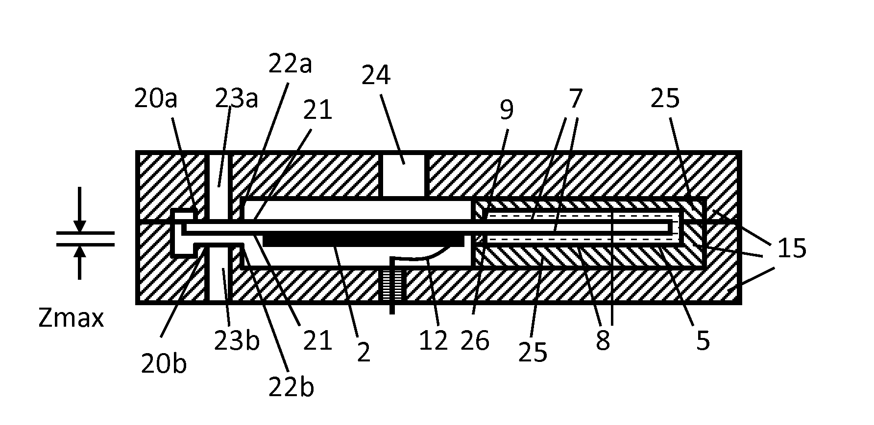
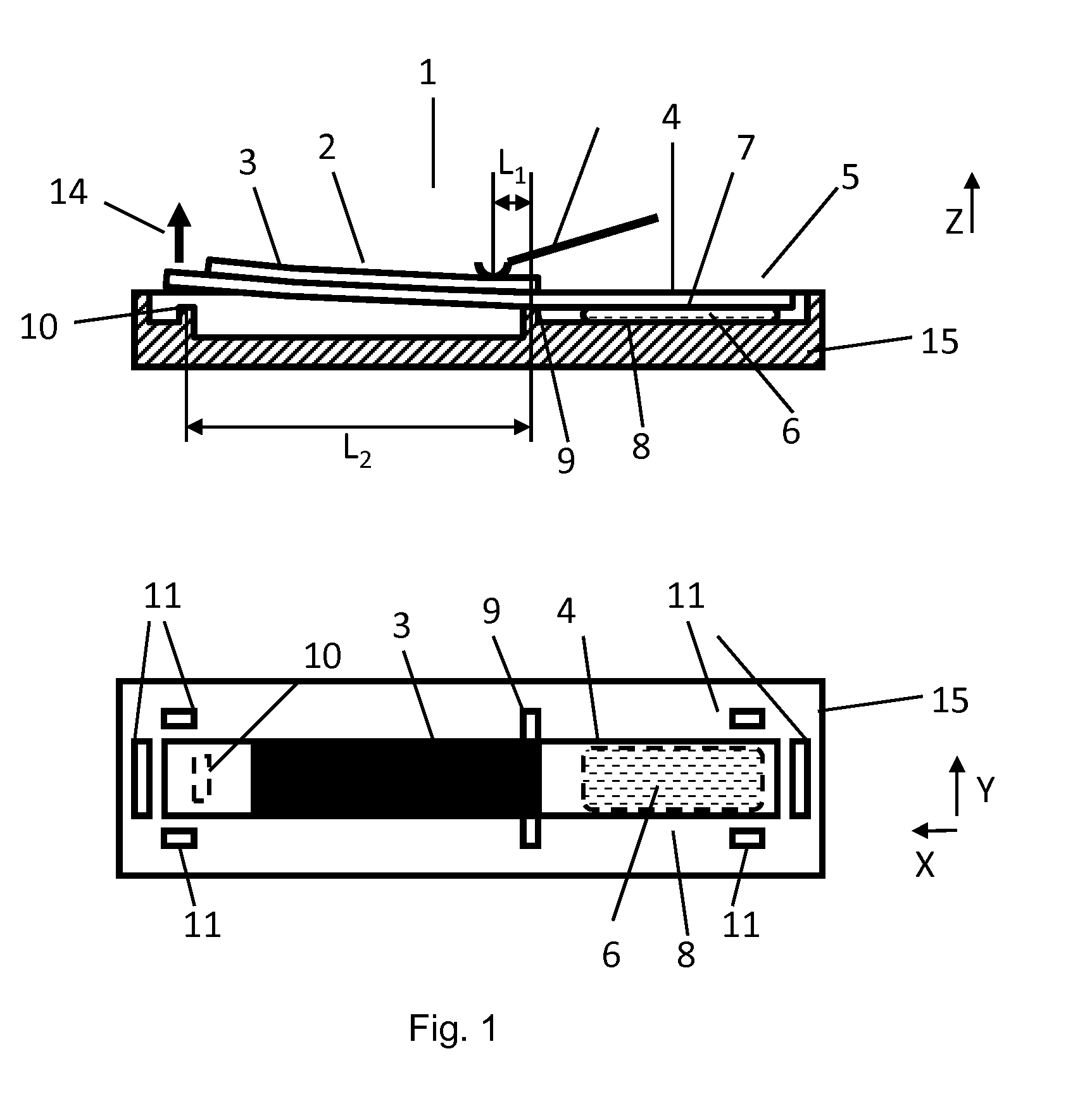
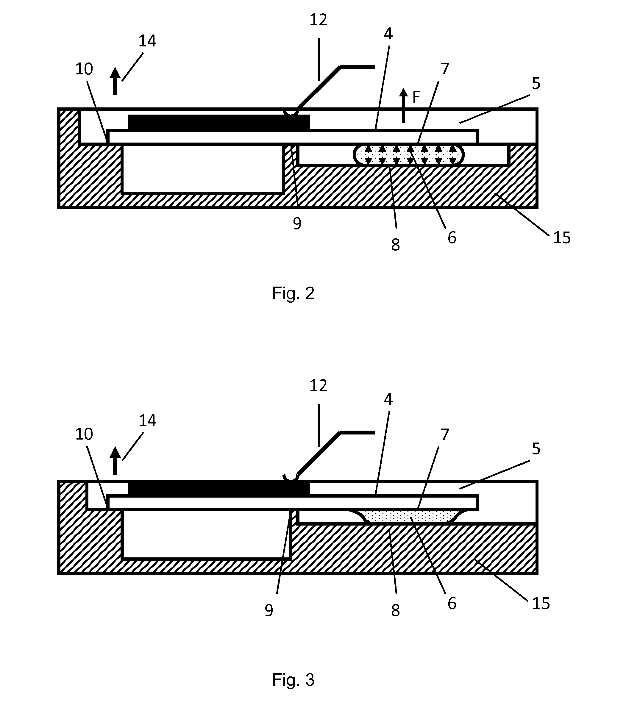
[0026]In FIG. 1 is sketched an embodiment of an actuation device 1 according to the invention, which contains a flexural transducer element 2 in a single- or multi-part housing 15, outlined schematically in a side sectional view and a top view. As a flexural transducer element within the context of this invention a coherent component shall be understood, which contains the piezoelectric flexural transducers. The basic structure and function of a piezo-electric flexural transducer is assumed to be known here. The eithin the invention preferably used monomorphic-flexural elements usually beside the active piezoelectric layer 3 contain a passive substrate layer 4 of an adequate solid, non-piezoelectric material. The active piezoelectric layer 3 in several preferred embodiments covers the substrate layer 4 only in sections. The substrate layer as part of the flexural transducer element 2 can, for example, include the sealing element of a valve, mounting structures, or parts or structure...


PUM


Abstract

It is introduced a miniaturizable actuation device based on piezoelectric flexural transducer element, which can be fabricated easily and cost effective, for use in a fluid valve or other devices, the actuation device being suited to perform reproducible actuation deflections fast and precisely, uneffected by disturbing influences due to temperature changes and mechanical deformations of the housing. The actuation device according to the invention includes a fluid bearing 5 with a first surface 7, which is associated with the flexural transducer element 2, a second surface 8, which is associated with the housing 15, and a flowable power transmitting fluid 6 between the surfaces, to transmit the reaction forces and—moments resulting from the actuatro deflection from the flexural transducer element 2 to the housing 15.

Description

TECHNICAL FIELD[0001]The invention relates to a miniature piezo flexural transducer element, in particular a miniature-valve system to control fluids using a piezoelectric flexural transducer element with a short response time.[0002]Piezoelectric flexural transducer elements are actuators for generating an actuator deflection 14 in a non-clamped area and are composed out of several material layers with at least one piezoelectric layer. The layers are particularly in the monomorph configuration characterized by different thermal expansion coefficients. Temperature changes, operation-related housing-deformations or aging processes can superimpose erratic deflections to the usable actuator deflection 14 with a magnitude in the same order, thus strongly affecting functionality of the actuator.BACKGROUND ART[0003]U.S. Pat. No. 6,581,638 describes a valve with a compact piezoelectric flexural transducer unit, comprising two at a pivot bearing jointly connected flexural elements with a com...

Claims


Application Information

Patent Timeline
Patent Type & Authority Applications(United States)
IPC IPC(8): F16K31/02H01L41/053
CPCF16K31/006H01L41/094H01L41/053H10N30/88H10N30/2042
Inventor BUESTGENS, BURKHARDGEORGES, SUHEEL
Owner EXEL IND SA
Why Eureka
Try Eureka