Seat

a seat and seat technology, applied in the field of seats, can solve problems such as material degradation or welding defects, and achieve the effects of improving strength, reducing the weight of each side frame, and increasing the section modulus

Active Publication Date: 2011-07-14
DELTA TOOLING CO LTD
View PDF26 Cites 28 Cited by
  • Summary
  • Abstract
  • Description
  • Claims
  • Application Information

AI Technical Summary

Benefits of technology

[0011]The seat according to the present invention has a configuration in which, in each side frame of a cushion frame, an inner frame and an outer frame which have flanges extending along peripheral edges thereof are faced to each other with a space therebetween at least partially, and the flanges are fixed along the entire peripheral edges thereof by hemming process. Since the entire peripheral edges are hemmed, the inner frame and the outer frame are securely fixed. In addition to this, since the inner frame and the outer frame are fixed to each other at at least one point by a fastening member, or the flanges hemmed are at least partially fixed to each other by adhesive, filler, or caulking, the inner frame and the outer frame are further securely fixed to each other. Additionally, since the inner frame and the outer frame which are thin-plate-shaped are used, reduction in weight of each side frame can be achieved. Further, since the inner frame and the outer frame are faced to each other with a space therebetween at least partially in order to increase in section modulus, a compressive / tensile strength required as a side frame can be secured by inserting an expanded bead body into the space. Incidentally, it is preferred that the inner frame and the outer frame have the space therebetween within as wide a facing range as possible. Thereby, a range in which the expanded bead body can be inserted in the space is increased, which results in improvement in strength. On the other hand, the expanded bead body is very light, and therefore it does not cause a large increase in weight. Further, since the flanges are subjected to hemming process, even thin plate frames obtain a three-layered medium thick plate structural body extending along the flanges hemmed, which results in increase in rigidity, and which makes a crack or a break from the peripheral edges unlikely.
[0012]Further, since each side frame of a back frame having a cantilever support structure normally is similarly formed from a thin-plate-shaped inner frame and a thin-plate-shaped outer frame, and these frames are fixed to each other by hemming process, weight reduction of the side frame can also be achieved even in the back frame. Further, when the hemming process is applied to form the side frame of the back frame, an upper end edge of the side frame is opened without applying the hemming process to the upper end edge, so that a pipe frame can be arranged inside the side frame. Then, this arrangement of the pipe frame inside the side fames can increase the strength of the back frame.

Problems solved by technology

That is, a frame is made by making two thin metal plates face each other and joining their end edge portions to each other, but, in a case where such a frame made of thin metal plates (a thin plate frame) is used, trying to couple the thin plate frames each having a thickness of, for example, 1.0 mm or less, with each other by welding is likely to cause material degradation or a welding defect, since the heat capacity is high.

Method used


Image

  • Seat
  • Seat
  • Seat

Examples


Embodiment Construction

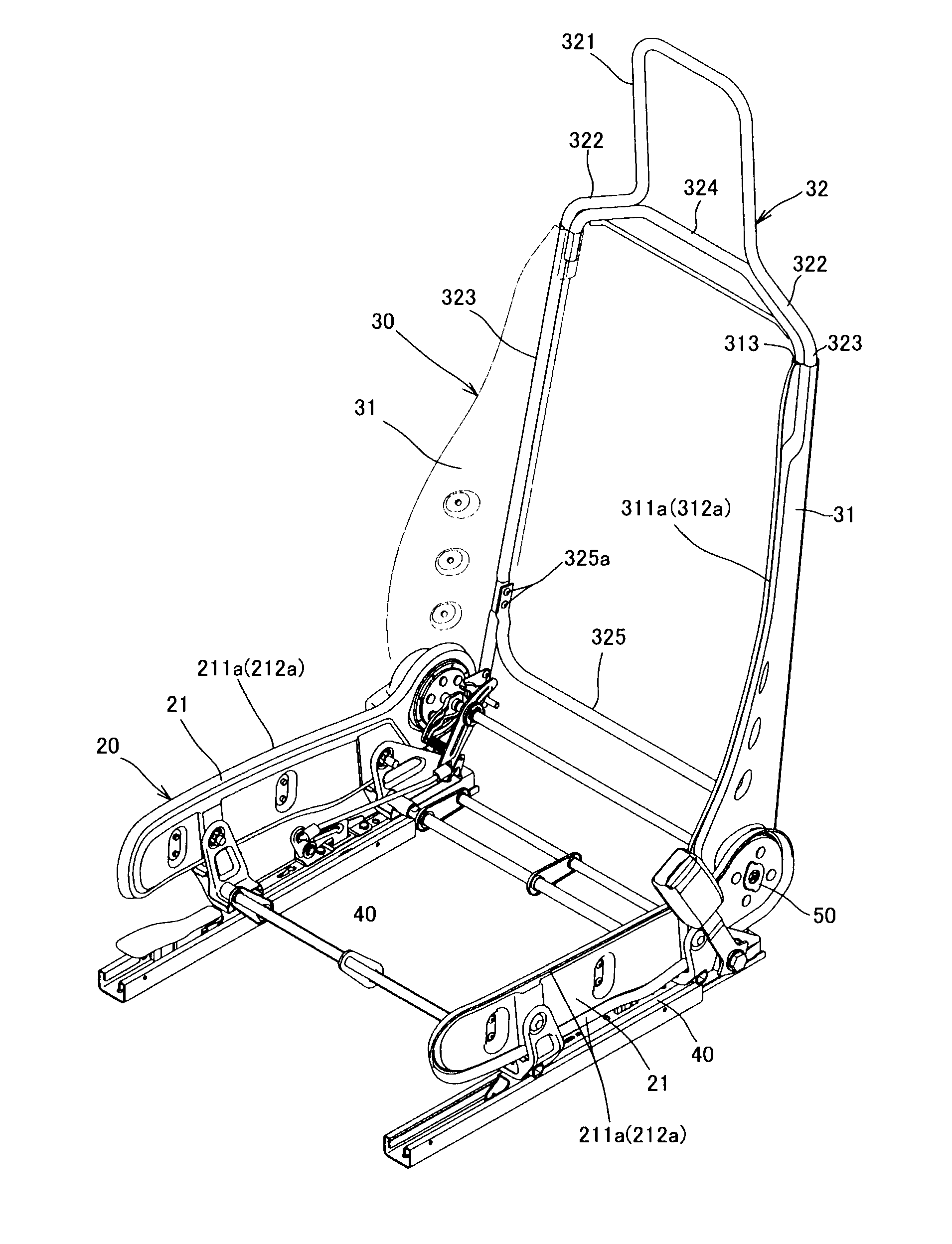
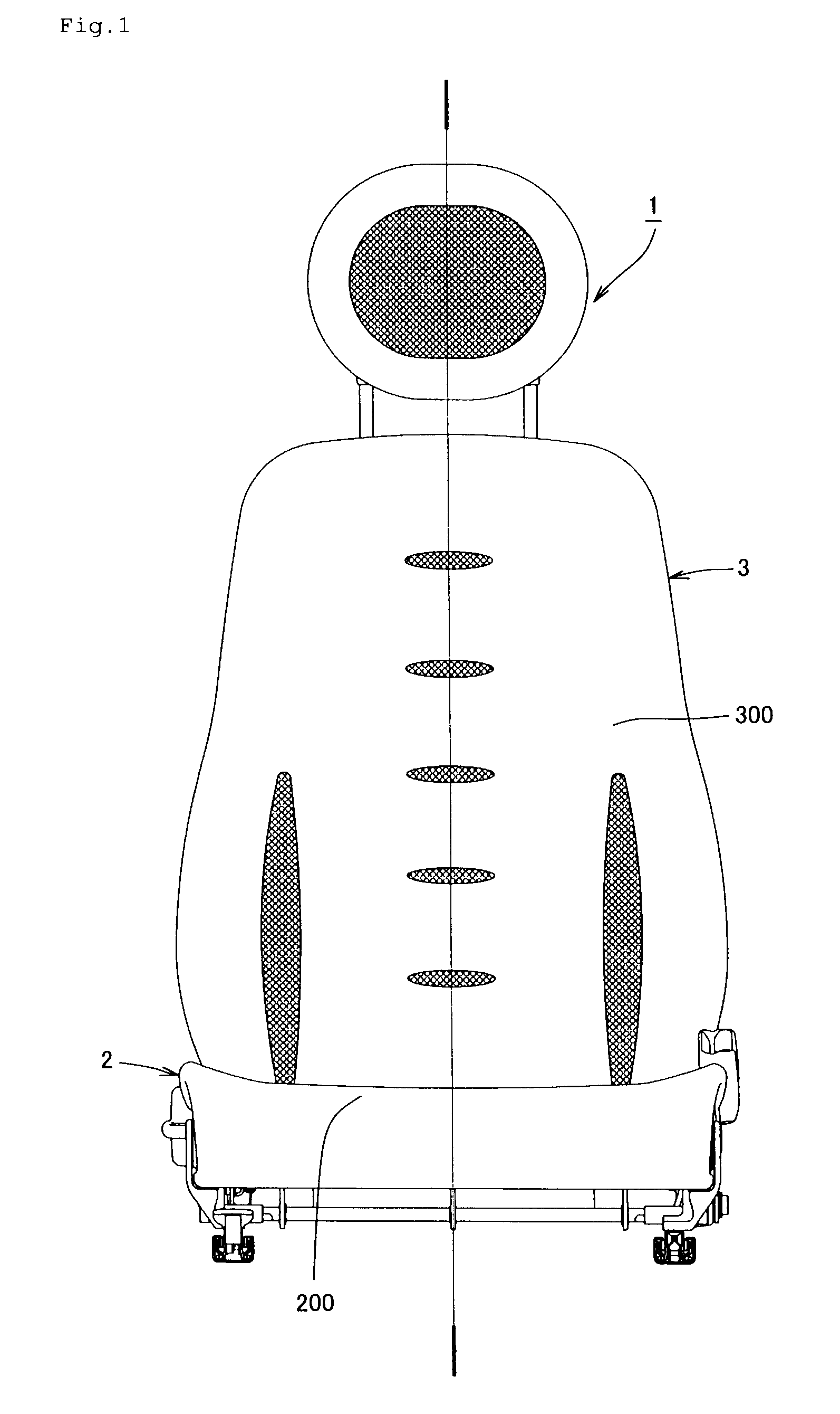
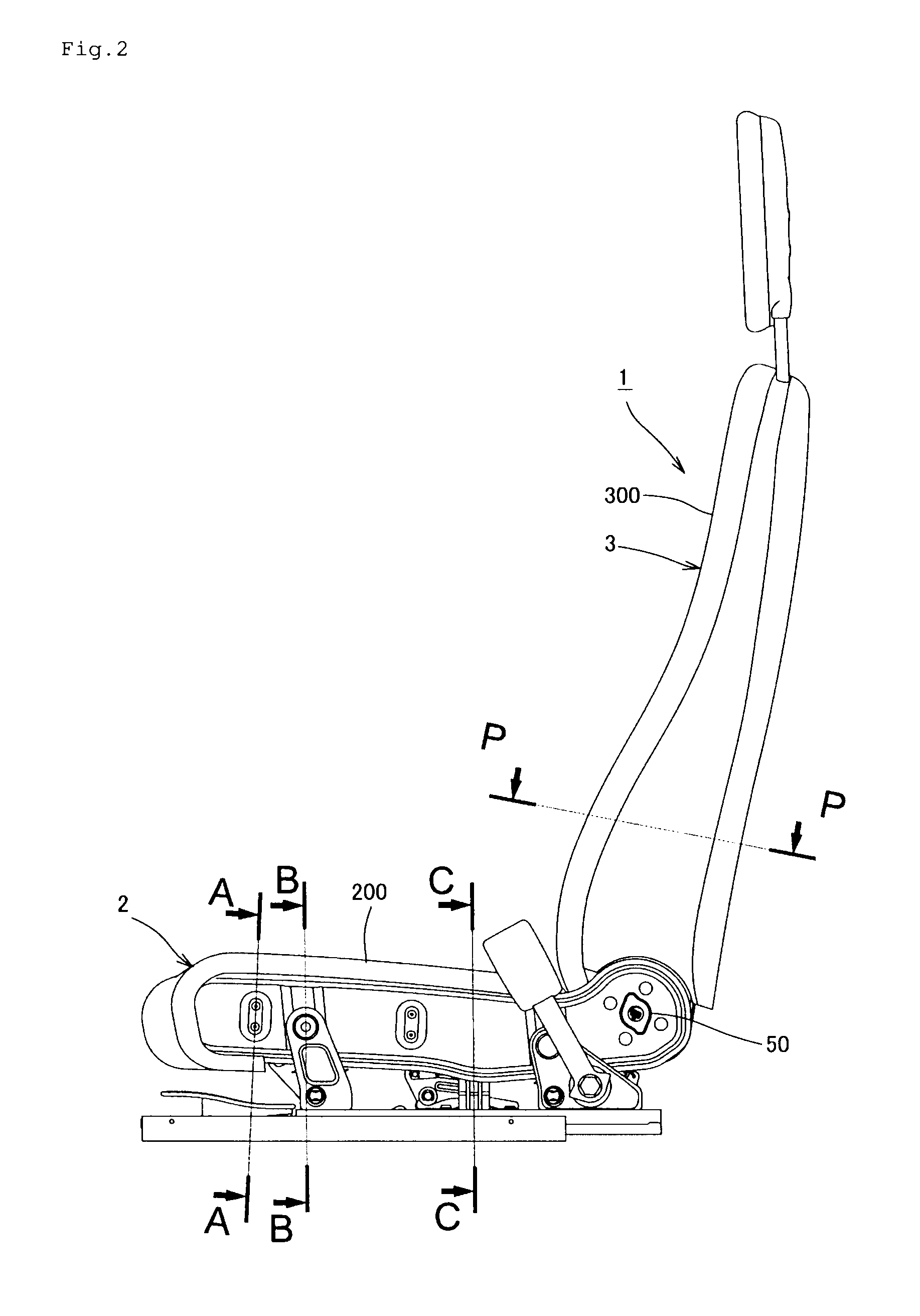
[0023]Hereinafter, embodiments of the present invention will be further explained in detail with reference to the drawings. FIG. 1 is a front view of a seat 1 according to the embodiment, FIG. 2 is a side view thereof, and FIG. 3 is a view showing a frame structure of the seat 1. As shown in these figures, the seat 1 is configured to be provided with a seat cushion section 2 and a seat back section 3. The seat cushion section 2 is configured to be provided with a cushion frame 20 and a cushioning member 200 supported by the cushion frame 20, and the seat back section 3 is configured to be provided with a back frame 30 and a cushioning member 300 supported by the back frame 30. The cushioning members 200 and 300 are stretched on the cushion frame 20 and the back frame 30 so as to be provided as tensile structural bodies. For example, a two-dimensional net, a three-dimensional solid knitted fabric, an expanded bead body to a surface of which a thin high-density urethane coating is app...


PUM


Abstract

A seat has a configuration in which, in each side frame of a cushion frame, an inner frame and an outer frame which have flanges extending along peripheral edges thereof are faced to each other with a space therebetween at least partially, and the flanges are fixed by hemming process along the entire peripheral edges thereof. Since the entire peripheral edges are hemmed, the inner frame and the outer frame are securely fixed. Additionally, since the inner frame and the outer frame which are thin-plate-shaped are used, reduction in weight of each side frame can be achieved. Further, since the inner frame and the outer frame are faced to each other with a space therebetween at least partially, a compressive / tensile strength required as a side frame can be secured by inserting an expanded bead body into the space.

Description

TECHNICAL FIELD[0001]The present invention relates to a seat used as a seat for a vehicle such as an airplane, a train, or an automobile, or an office chair, or the like.BACKGROUND ART[0002]In recent years, in view of improvement of fuel efficiency or the like, expectations of weight reduction of a vehicle such as a vehicle body or an airframe have increased. For this reason, a technique to use a three-dimensional solid knitted fabric, which is lighter than urethane foam, as a cushioning member even in a seat used in those vehicles, or the like, has also been considered. However, not only such weight reduction of a cushioning member, but also further thinning of a metal plate used as a frame can also be thought as a way to reduce the weight of a seat. That is, a frame is made by making two thin metal plates face each other and joining their end edge portions to each other, but, in a case where such a frame made of thin metal plates (a thin plate frame) is used, trying to couple the ...

Claims


Application Information

Patent Timeline
Patent Type & Authority Applications(United States)
IPC IPC(8): A47C7/02B60N2/68B60N2/90
CPCA47C7/02A47C7/282A47C7/40B60N2/686B60N2/68B60N2/682A47C31/006
Inventor FUJITA, ETSUNORIOGURA, YUMIKAWASAKI, SEIJISUGIMOTO, EIJIMAKITA, SOICHITAKATA, YASUHIDEMAEDA, SHIGERUMATSUKAWA, RYOJIYAMANE, HIDEYUKIYOSHIDA, SEIYA
Owner DELTA TOOLING CO LTD
Why Eureka
Try Eureka