Video display system
a video display and video technology, applied in the field of video display systems, can solve the problems of flicker generation, unpleasant impression of observers, etc., and achieve the effects of reducing crosstalk, reducing contrast of shutter eyeglasses, and facilitating optimization
- Summary
- Abstract
- Description
- Claims
- Application Information
AI Technical Summary
Benefits of technology
Problems solved by technology
Method used
Image
Examples
embodiment
Whole Structure of Video Display System
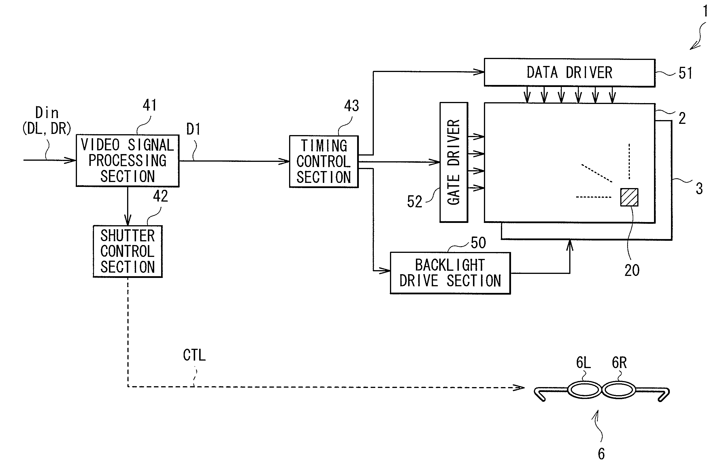
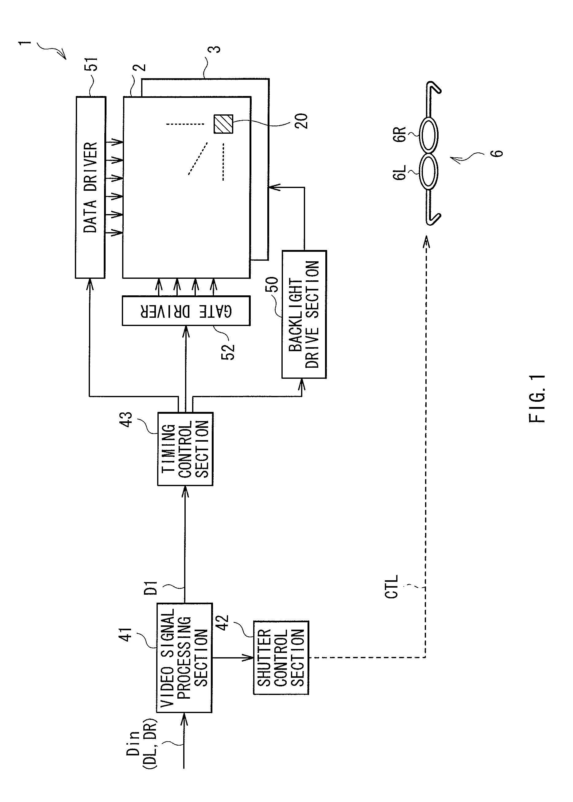
[0026]FIG. 1 illustrates a block structure of a video display system according to an embodiment of the invention. The video display system is a time divisional driving method stereoscopic video display system. The video display system includes a liquid crystal display unit 1 as a video display unit and shutter eyeglasses 6.
[0027]Liquid Crystal Display Unit 1
[0028]The liquid crystal display unit 1 displays a video based on an input video signal Din composed of a right-eye video signal DR and a left-eye video signal DL having right and left parallax. The liquid crystal display unit 1 has a liquid crystal display panel 2, a backlight 3, a video signal processing section 41, a shutter control section 42, a timing control section 43, a backlight drive section 50, a data driver 51, and a gate driver 52.
[0029]The backlight 3 is a light source that illuminates the liquid crystal display panel 2 with light. For example, the backlight 3 includes an LED (...
examples
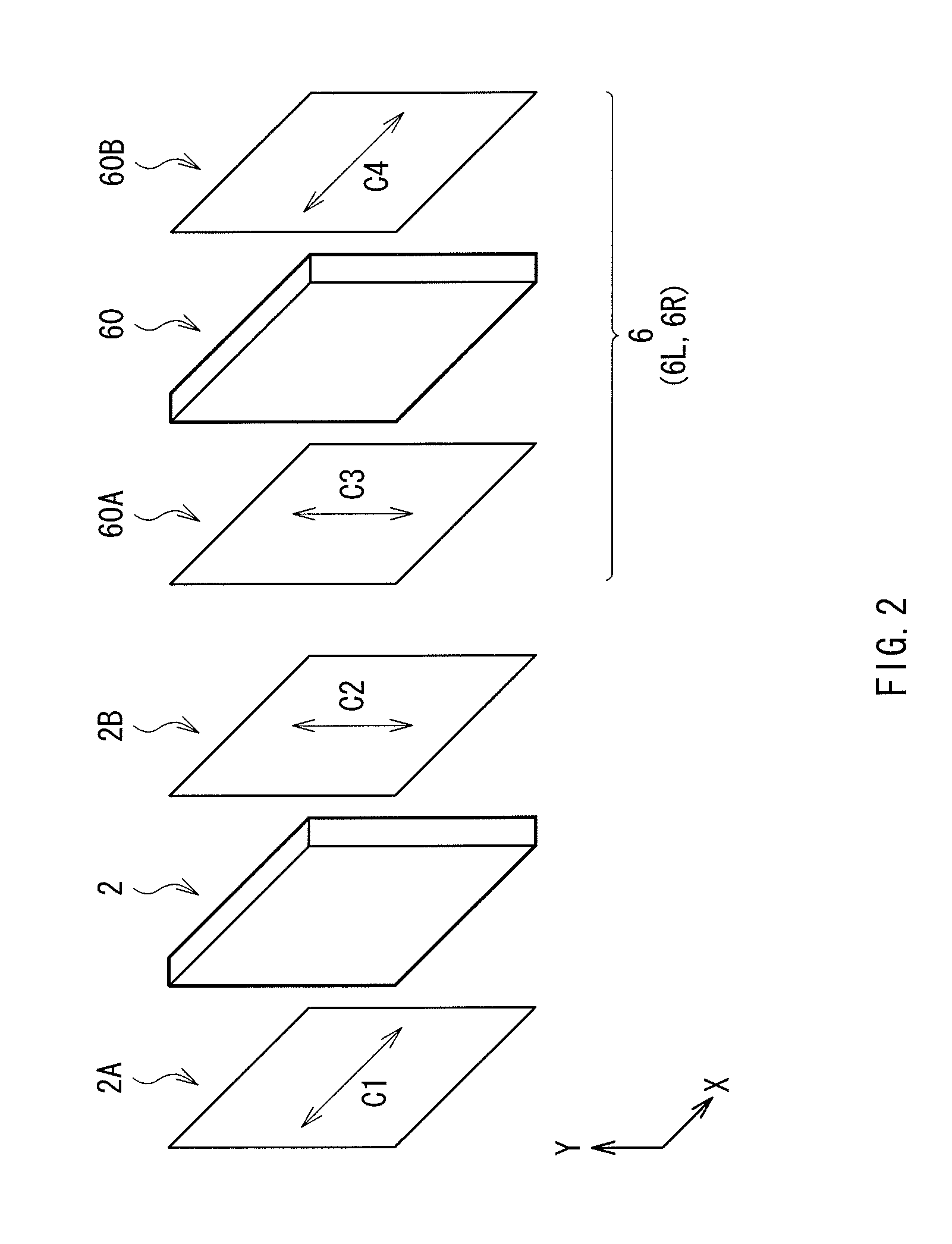
[0062]A description will be given of specific examples (Examples 1 to 3) in this embodiment. As Examples 1 to 3, the shutter eyeglasses 6 with the contrast CR different from each other were fabricated. Generation state of flicker and crosstalk in the fabricated shutter eyeglasses 6 was quantitatively examined, and was subjectively evaluated by human eyes. The contrast CR in the shutter entrance-side polarization plate 60A was 9.8 in Example 1, 3.2 in Example 2, and 2.2 in Example 3. As the backlight 3, an LED was used and driven in a manner of blinking (duty in lighting time period: 25%). The shutter aperture duty in the shutter eyeglasses 6 was 50% except for the case particularly mentioned. Further, for a case that a high contract (CR=1000) polarization plate was provided on the shutter entrance side as Comparative example 1 of these Examples 1 to 3 and a case that a polarization plate was not provided on the shutter entrance side as Comparative example 2, measurement similar to t...
modified example
[0069]FIGS. 11A and 11B schematically illustrate general outline of video display operation in a video display system (multi view system) according to a modified example of the foregoing embodiment. In this modified example, video display operation capable of individually displaying a plurality of (two in this case) video streams that are different from each other to a plurality of observers (two observers in this case) is performed instead of the stereoscopic video display operation described above. For elements similar to those of the foregoing embodiment, the same referential symbols are affixed thereto, and description thereof is omitted as appropriate.
[0070]In the multi view system of this modified example, a first video based on a first video signal corresponding to a first observer and a second video based on a second video signal corresponding to a second observer are time-divisionally and alternately displayed. In other words, in the foregoing description, the left-eye vide...
PUM
 Abstract
Description
Claims
Application Information
 - R&D
- Intellectual Property
- Life Sciences
- Materials
- Tech Scout
- Unparalleled Data Quality
- Higher Quality Content
- 60% Fewer Hallucinations
Browse by: Latest US Patents, China's latest patents, Technical Efficacy Thesaurus, Application Domain, Technology Topic, Popular Technical Reports.
© 2025 PatSnap. All rights reserved.Legal|Privacy policy|Modern Slavery Act Transparency Statement|Sitemap|About US| Contact US: help@patsnap.com


