
Scanner motor

a scanner motor and motor housing technology, applied in the direction of sliding contact bearings, mechanical equipment, instruments, etc., can solve the problems of high-speed rotation of the disk drive for driving the device, noise, and noise, and achieve the noise level required by the lsu or the printer set. achieve the effect of long life and stability

Inactive Publication Date: 2011-07-14
SAMSUNG ELECTRO MECHANICS CO LTD
View PDF8 Cites 6 Cited by
  • Summary
  • Abstract
  • Description
  • Claims
  • Application Information

AI Technical Summary

Benefits of technology

[0010]The present invention has been made in an effort to provide a scanner motor which is capable of acquiring a long lifespan and stability even in super high-speed rotation.

Problems solved by technology

Therefore, disk drives for driving the devices require high-speed rotation.
The high-speed rotation inevitably leads to noise.
In addition to noise generated by friction between the scanner motor and the air according to the rotating speed, an LSU or a printer set is resonated or excited because of the unbalanced mass of the scanner motor, thus causing noise.
Thus, in the process of manufacturing the scanner motor, the unbalanced mass is controlled, thus achieving a noise level which is required by the LSU or printer set.

Method used


Image

  • Scanner motor
  • Scanner motor
  • Scanner motor

Examples


Embodiment Construction

[0022]The terminology or words used in the description and the claims of the present invention should not be interpreted as being limited merely to common or dictionary meanings. On the contrary, they should be interpreted based on the meanings and concepts of the invention in keeping with the scope of the invention on the basis of the principle that the inventor(s) can appropriately define the terms in order to describe the invention in the best way.

[0023]Hereinafter, scanner motors according to the preferred embodiments of the present invention will be described in detail with reference to the accompanying drawings.

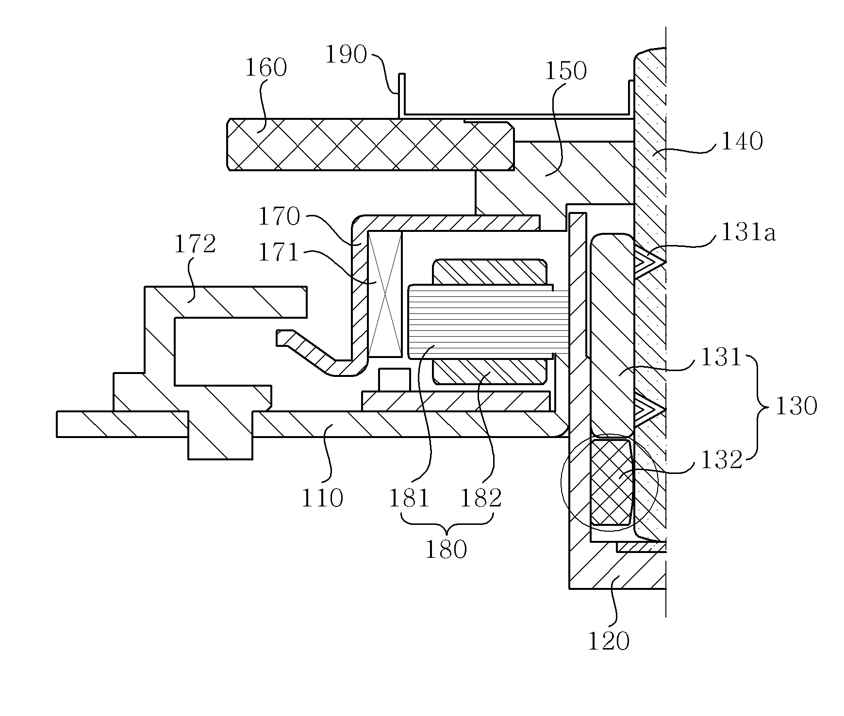
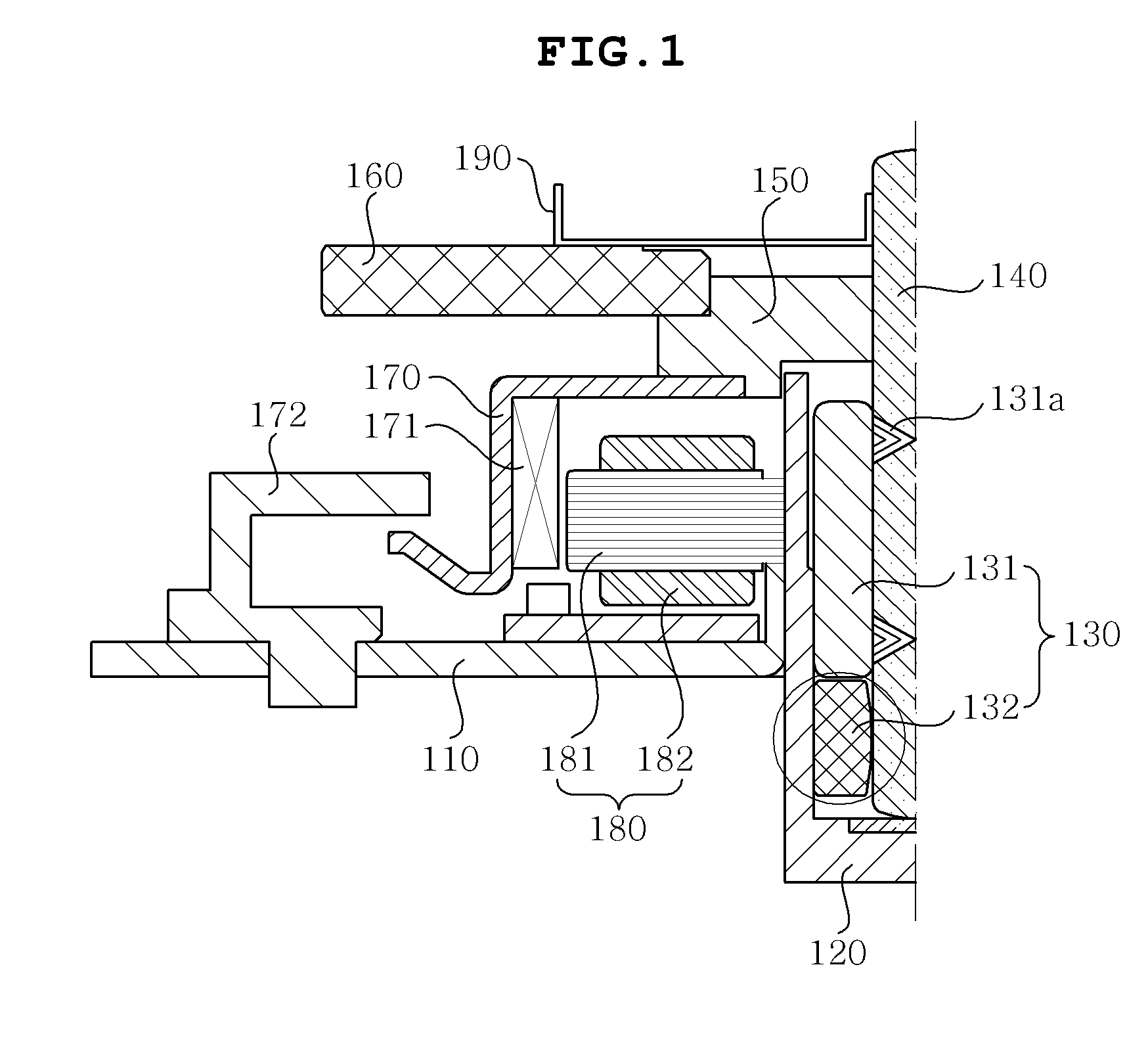
[0024]FIGS. 1 and 2 show only half of a scanner motor for convenience of description. The scanner motor has a bilateral symmetric structure.

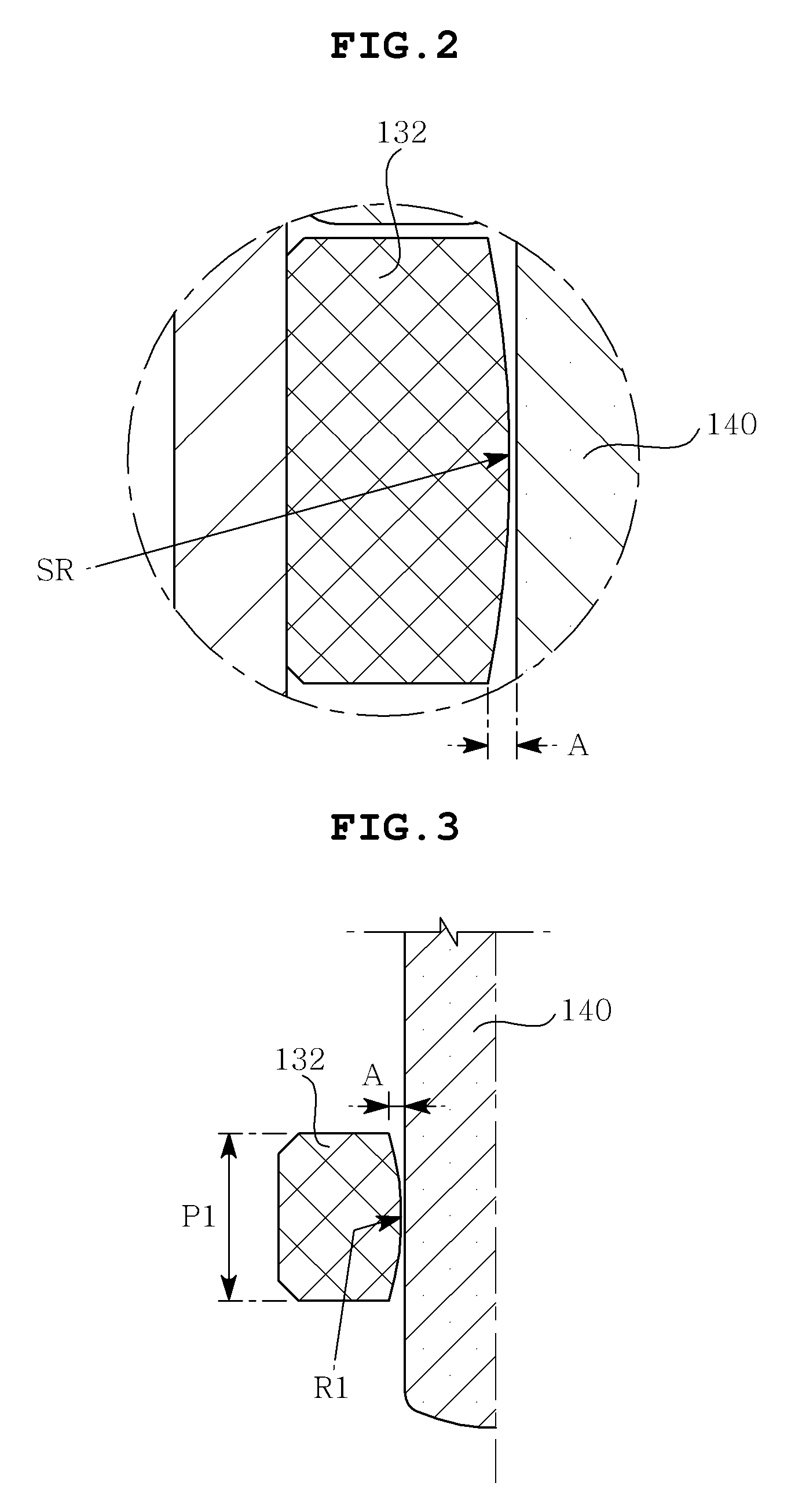
[0025]FIG. 1 is a sectional view illustrating a scanner motor according to a preferred embodiment of the present invention, and FIG. 2 is a partial enlarged view illustrating a bearing of the scanner motor. Hereinafter, the scanner ...


PUM


Abstract

Disclosed herein is a scanner motor. The scanner motor includes a rotating shaft which is axially supported and rotatable, and a bearing which has the shape of a hollow cylinder. The bearing includes a hydrodynamic bearing portion provided on the upper portion of the bearing to rotatably support the rotating shaft, and an oil impregnated sintered bearing portion provided on the lower portion of the bearing.

Description

CROSS REFERENCE TO RELATED APPLICATION[0001]This application claims the benefit of Korean Patent Application No. 10-2010-0001735, filed on Jan. 8, 2010, entitled “SCANNER MOTOR”, which is hereby incorporated by reference in its entirety into this application.BACKGROUND OF THE INVENTION[0002]1. Field of the Invention[0003]The present invention relates to a scanner motor.[0004]2. Description of the Related Art[0005]Recently, as electronic devices have developed, high-capacity data storage devices including a compact disk (CD), a digital versatile disk (DVD), a blu-ray disk (BD), and a high definition (HD) DVD have been used. Therefore, disk drives for driving the devices require high-speed rotation.[0006]A polygon mirror scanning motor (hereinafter, referred to as a scanner motor) is mounted to a laser scanning unit of a laser beam printer to deflect a laser beam.[0007]The motor is equipped with a polygon minor and is rotated at high speed to reflect a laser beam having printing infor...

Claims


Application Information

Patent Timeline
IPC IPC(8): G02B26/10
CPCF16C17/02F16C33/128G02B26/121F16C41/008F16C17/026F16C33/104F16C17/26H02K5/1675F16C2380/26
Inventor SONG, SANG JAEBAE, YOUNG JINOH, SONG BON
Owner SAMSUNG ELECTRO MECHANICS CO LTD
Learn More