Cold cathode illumination apparatus

a technology of illumination apparatus and cold cathode, which is applied in the direction of transit-tube circuit elements, cathode-ray/electron beam tube circuit elements, structural circuit elements, etc., can solve the problems of users inconvenient use and tardy lighting up, and achieve the ability of dimming, improve the efficiency of light usage, and prolong the life

Inactive Publication Date: 2010-07-22
AUSK OPTOELECTRONICS
View PDF1 Cites 2 Cited by
  • Summary
  • Abstract
  • Description
  • Claims
  • Application Information

AI Technical Summary

Benefits of technology

[0009]In view of the foregoing subject, an object of the invention is to provide an illumination apparatus that is prompt in lighting up and has a long lifespan.
[0011]As mentioned above, the cold cathode illumination apparatus according to the invention has a tube in which at least one CCFL is disposed. Because the electrode of the CCFL is not made of wolfram, the lighting up speed of the CCFL is prompter than that of HCFL. In addition, the CCFL has other advantages, such as long lifespan, and capability of dimming and ability to turn on and off frequently and rapidly. Besides, the reflective surface of the string element can reflect the downward light emitted by the CCFL to the upside to improve the efficiency of the light usage.

Problems solved by technology

However, due to a long period of preheating the filaments 12 of the HCFL 1, the lighting up is tardy.
Besides, some drawbacks of HCFL 1, such as short lifespan, difficulty in dimming and inability to turn on and off frequently, all make users inconvenient in usage.

Method used


Image

  • Cold cathode illumination apparatus
  • Cold cathode illumination apparatus
  • Cold cathode illumination apparatus

Examples


first embodiment

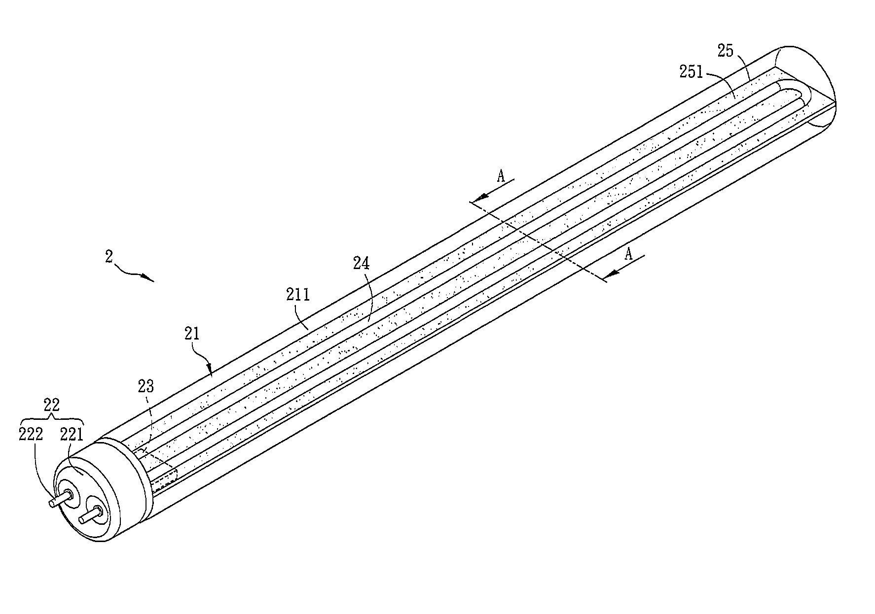
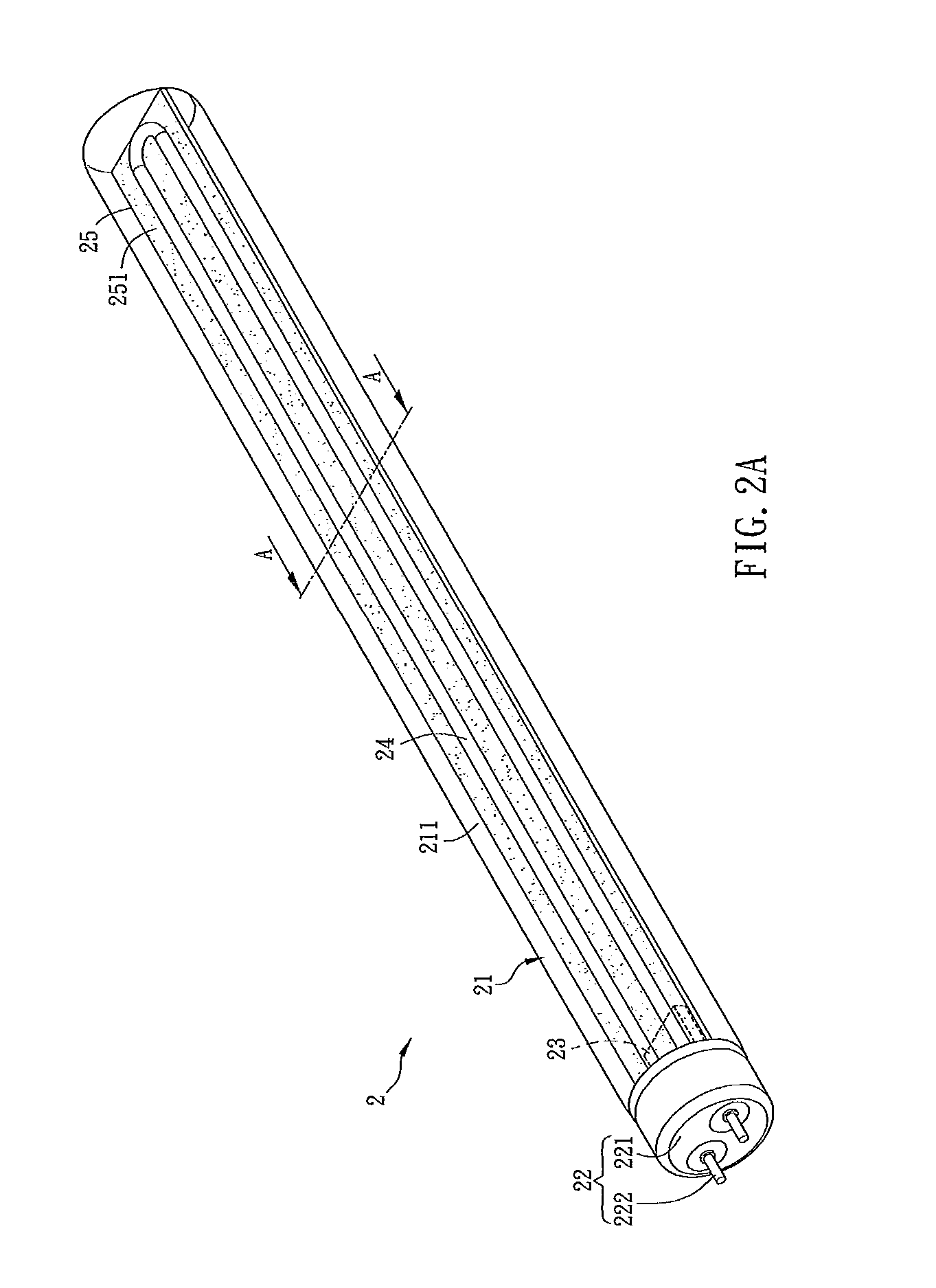
[0027]FIG. 2A is a schematic view of a cold cathode illumination apparatus 2 according the first embodiment of the invention, and FIG. 2B is a sectional diagram taken along the section A-A in FIG. 2A. Referring to FIGS. 2A and 2B, the cold cathode illumination apparatus 2 is applied with an alternative current (AC), which is, for example, the AC with 60 Hz supplied from the city power or the AC outputted by other electronic devices such as inverters, electronic ballasts and electromagnetic ballasts. To be noted, the AC compliant with high frequency, low frequency or other frequencies is applicable. Among them, the high frequency range may be between 1 KHz and 1000 KHz, and is preferably between 20 KHz and 30 KHz or between 40 KHz and 70 KHz.

[0028]The cold cathode illumination apparatus 2 includes a tube 21, at least one electrical connection element 22, a voltage transforming element 23, a CCFL 24 and a strip element 25.

[0029]At least a part of the tube 21 is light-permeable. The tu...

second embodiment

[0045]FIG. 3 shows a cold cathode illumination apparatus 3 according to the second embodiment of the invention. The main difference between the cold cathode illumination apparatus 3 and the first embodiment is that the cold cathode illumination apparatus 3 includes two electrical connection elements 32, which are disposed at two ends of the tube 31 respectively, and each electrical connection element 32 has a lamp cap 321 and two electrode pins 322. Besides, the cold cathode illumination apparatus 3 further has two linear CCFLs 34 and two strip elements 35. The CCFLs 34 are adhered to the tube 31 parallely. Each of the strip elements 35 has a Y-shaped cross-section, and is used as the supporter of the CCFL 34.

[0046]Therefore, the cold cathode illumination apparatus 3 can be directly connected to the present electronic ballast, and receive the high frequency power outputted by the electronic ballast, thereby enhancing the usage convenience and saving the cost of altering the circuit....

third embodiment

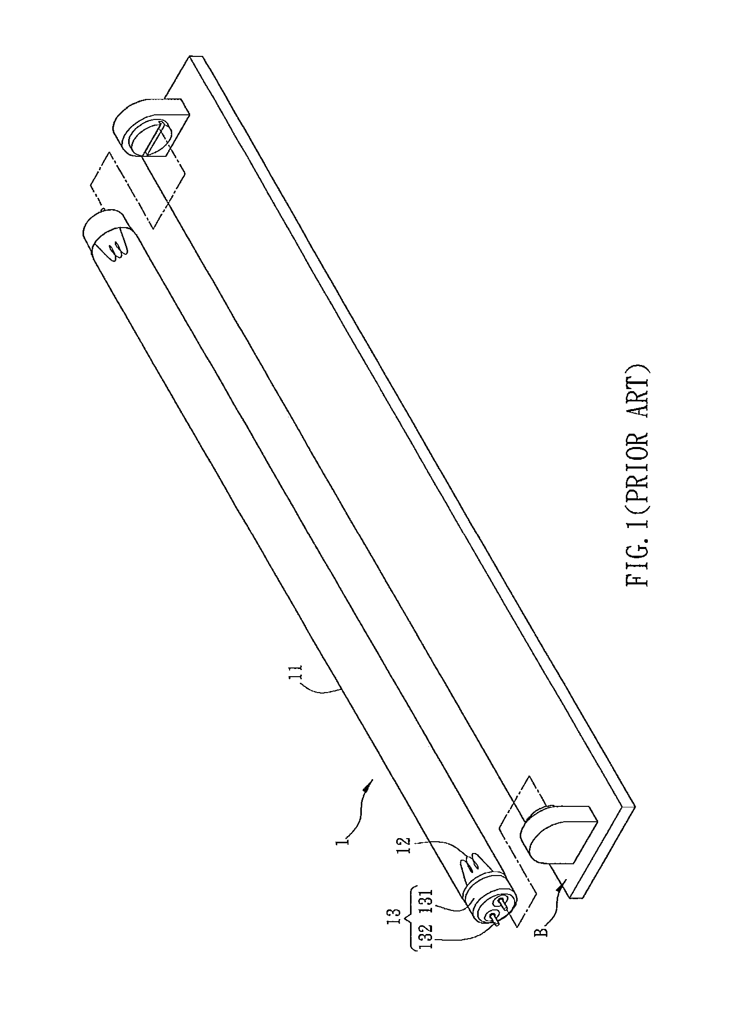
[0049]FIG. 6A is a schematic view of the cold cathode illumination apparatus 4 cooperated with the lamp base B, and FIG. 6B is a sectional view of the cold cathode illumination apparatus 4 taken along the section B-B in FIG. 6A. As shown in FIGS. 6A and 6B, the main difference between the cold cathode illumination apparatus 4 of the third embodiment and the first embodiment is that the cold cathode illumination apparatus 4 includes two electrical connection elements 42 which are disposed at two ends of the tube 41 respectively, and each electrical connection element 32 has a lamp cap 421 and two electrode pins 422. Besides, the cold cathode illumination apparatus 4 can further have at least one circuit board 46 and at least one supporting element 47.

[0050]The circuit board 46 is disposed in the tube 41, and located at the side opposite to the CCFL 44, for example. Of course, the circuit board 46 can be disposed at the same side as the CCFL 44. The tube 41 can have a light-permeable ...


PUM


Abstract

A cold cathode illumination apparatus applied with an alternative current includes a tube, at least one electrical connection element, a voltage transforming element, a cold cathode fluorescent lamp (CCFL) and a strip element. At least one part of the tube is light-permeable. The electrical connection element is disposed at one end of the tube. The voltage transforming element is disposed in the tube and electrically connected with the electrical connection element. The CCFL is disposed in the tube and electrically connected with the voltage transforming element. The strip element is disposed along and in the tube. The CCFL is connected with the strip element. The strip element has a reflective surface above which the CCFL is disposed.

Description

CROSS REFERENCE TO RELATED APPLICATIONS[0001]This Non-provisional application claims priority under 35 U.S.C. §119(a) on Patent Application No(s). 098101954 and 098109001 filed in Republic of China on Jan. 19, 2009 and Mar. 19, 2009, the entire contents of which are hereby incorporated by reference.BACKGROUND OF THE INVENTION[0002]1. Field of Invention[0003]The invention relates to an illumination apparatus and, in particular, to a cold cathode illumination apparatus.[0004]2. Related Art[0005]With the progress of technology, illumination apparatuses have become indispensible electric equipment in our daily life. Among present technologies, most illumination apparatuses use hot cathode fluorescent lamps (HCFL) as the lighting source.[0006]FIG. 1 is a schematic view of a conventional HCFL 1 cooperated with a lamp base B. The HCFL 1 has a glass tube 11, two filaments 12 and two electrical connection elements 13. Argon which is easy to discharge and a few amount of mercury are introduce...

Claims


Application Information

Patent Timeline
Patent Type & Authority Applications(United States)
IPC IPC(8): H01J13/46
CPCH01J61/02H01J61/92H01J61/78
Inventor LIN, CHUNG-JYH
Owner AUSK OPTOELECTRONICS
Why Eureka
Try Eureka