Composite electrode material and method for manufacturing the same

a technology of composite electrodes and electrodes, which is applied in the direction of cell components, instruments, optical radiation measurement, etc., can solve the problems of simple graphite electrodes that cannot meet the needs of the public, cracking of graphite and capacity loss, and irreversible capacity loss, etc., to achieve excellent capacity, cycle life, and efficiency.

Active Publication Date: 2019-02-28
NAT CHENG KUNG UNIV
View PDF3 Cites 2 Cited by
  • Summary
  • Abstract
  • Description
  • Claims
  • Application Information

AI Technical Summary

Benefits of technology

[0006]One objective of the present invention is to provide a novel composite electrode material and method for manufacturing the same, a composite electrode comprising said composite electrode material, and a Li-based battery comprising said composite electrode. The novel composite electrode material uses silicon or Si-based compounds coated with carbon nanotubes (CNT) or carbon fibers (CF). Thereby, the Li-based battery has an excellent capacity, efficiency, and cycle life after repeated charge / discharge.
[0010]According to the composite electrode material and method for manufacturing the same of the present invention, the material of the core preferably is Si in order to provide a high capacity value. Further, shape and size of the core are not limited. Preferably, the core is a thin sheet of paper-like silicon flake. Since a thin silicon flake is more elastic and flexible, it is not easily broken during charge / discharge. Further, by comparing a silicon flake with all the smaller silicon particles formed when the silicon flake is broken or pulverized, the total volume and weight are the same, but the broken or pulverized smaller silicon particles exhibit a much larger total surface area than that of a silicon flake. As a result, there is a decrease in the consumption of the electrolyte for forming SEI on the surface of a sheet of paper-like silicon flake, and it benefits longer battery lifespan. In addition, the size of the core is not limited. Preferably, a thickness of the core is in a range from 50 nm to 500 nm, and more preferably 50 nm to 250 nm; and / or the length or width of the core are preferably in a range from 100 nm to 9 μm, more preferably 500 nm to 1200 nm.
[0011]In addition, the carbon nanotube or the carbon fiber may grow upright or at various angles on a surface of the core, and the excess carbon nanotubes or carbon fibers may grow on other CNT or CF to form a three-dimensional (3D) porous mesh or sponge-like structure of the CNT or CF coated silicon particles. The structure of the 3D porous shaped CNT or CF may have buffer functions for multiple and multi-directional expansion / contraction of silicon. Thereby, it may reduce pulverization of the silicon resulting from the change of volume during charge / discharge. Furthermore, electrons may conduct along the conductive carbon nanotubes or carbon fibers to enhance the efficiency of the conduction path. Hence, the carbon nanotubes or carbon fibers disposed on the broken particles may also provide additional conduction paths for connecting the silicon particles to neighboring silicon particles and to a current collector of the battery even if the silicon particles are broken into smaller particles. At the same time, carbon nanotubes or carbon fibers may also protect the silicon to avoid excessive reactions with the electrolytic solution, and thus may remain high electrode capacity as well as improve cycle life of the battery.
[0020]In a common manufacturing method of silicon-based electrode, it is necessary to additionally add auxiliary materials, such as carbon black, for conduction so as to enhance the conduction of electrons between silicon particles as well as to the current collector. However, not like carbon nanotubes or carbon nanofibers, the additional carbon black may increase the weight and volume of the electrode rather than providing buffer functions for expansion / contraction of the silicon particles. On the contrary, since the electrons may be conducted along the carbon nanotubes or carbon fibers, an additional conductive path may be provided. Therefore, in one preferred embodiment of the present invention, even though the carbon black may not be added to support conduction path when manufacturing the composite electrode, the composite electrode remains original capacity at a constant capacity of 2000 mAhg−1 after charge / discharge for 100 times. Not like the silicon electrode without carbon nanotubes or carbon fibers coating on, the capacity of the composite electrode may not significantly drop after repeated charge / discharge.
[0022]As described above, the composite electrode material of the present invention has a unique structure, which directly grows the carbon nanotubes or carbon fibers on the surface of the core to form 3D porous carbon nanotubes or carbon fibers coating on silicon nanoparticles. Thereby, it can buffer stress resulted from volume changes of the core material during charge / discharge, and avoid over-reaction between the core and the electrolytic solution in order to increase battery's cycle count. At the same time, carbon nanotubes or carbon fibers can provide conductive path, so that electrons conduct along the carbon nanotubes or carbon fibers to enhance the efficiency of the conduction path. Therefore, it remains excellent charge / discharge characteristics even without adding carbon black during manufacturing of the composite electrode. As a result, the Li-based battery provided by the present invention has a longer battery cycle life and a higher capacity. Moreover, it still has excellent charge / discharge characteristics and Coulomb efficiency after repeated cycles.
[0023]As described above, the composite electrode material of the present invention has a unique structure, which directly grows the carbon nanotubes or carbon fibers on the surface of the core to form 3D porous carbon nanotubes or carbon fibers coating on silicon nanoparticles. This manufacturing method overcomes the difficulties in evenly mixing pre-synthesized carbon nanotubes and carbon fibers with silicon particles because carbon nanotubes and carbon fibers are easy in forming clusters and difficult to be separated for mixing evenly with silicon particles. Moreover, carbon nanotubes and carbon fibers directly grown on silicon provide higher electrical conductance between silicon particles and carbon nanotubes and carbon fibers in comparison with a mixture of silicon particles with pre-synthesized carbon nanotubes and carbon fibers which are easily forming clusters. Furthermore, separately synthesized carbon nanotubes and carbon fibers only loosely touch silicon particles resulting in less desirable and higher electrical resistance.

Problems solved by technology

A solid electrolyte interphase (SEI) will be formed on the surface after the first charge of the battery resulting in an irreversible capacity loss.
Furthermore, repeated charge / discharge process also generates gaps between graphite layers leading to cracking of the graphite and capacity loss.
With the advance of science and technology, simple graphite electrode is unable to meet the needs of the public.
Therefore, it is likely to cause pulverization of silicon.
Because electrons cannot be transported to or from broken and electrically isolated silicon particles, positively charged lithium ions also cannot be added or removed from those broken and electrically isolated silicon particles.
The electrolyte is finally depleted due to the formation of more and more SEI on increasing new surfaces of pulverized silicon, resulting in a shortened battery lifespan.

Method used


Image

  • Composite electrode material and method for manufacturing the same
  • Composite electrode material and method for manufacturing the same
  • Composite electrode material and method for manufacturing the same

Examples


preparation example 1

osite Electrode Material

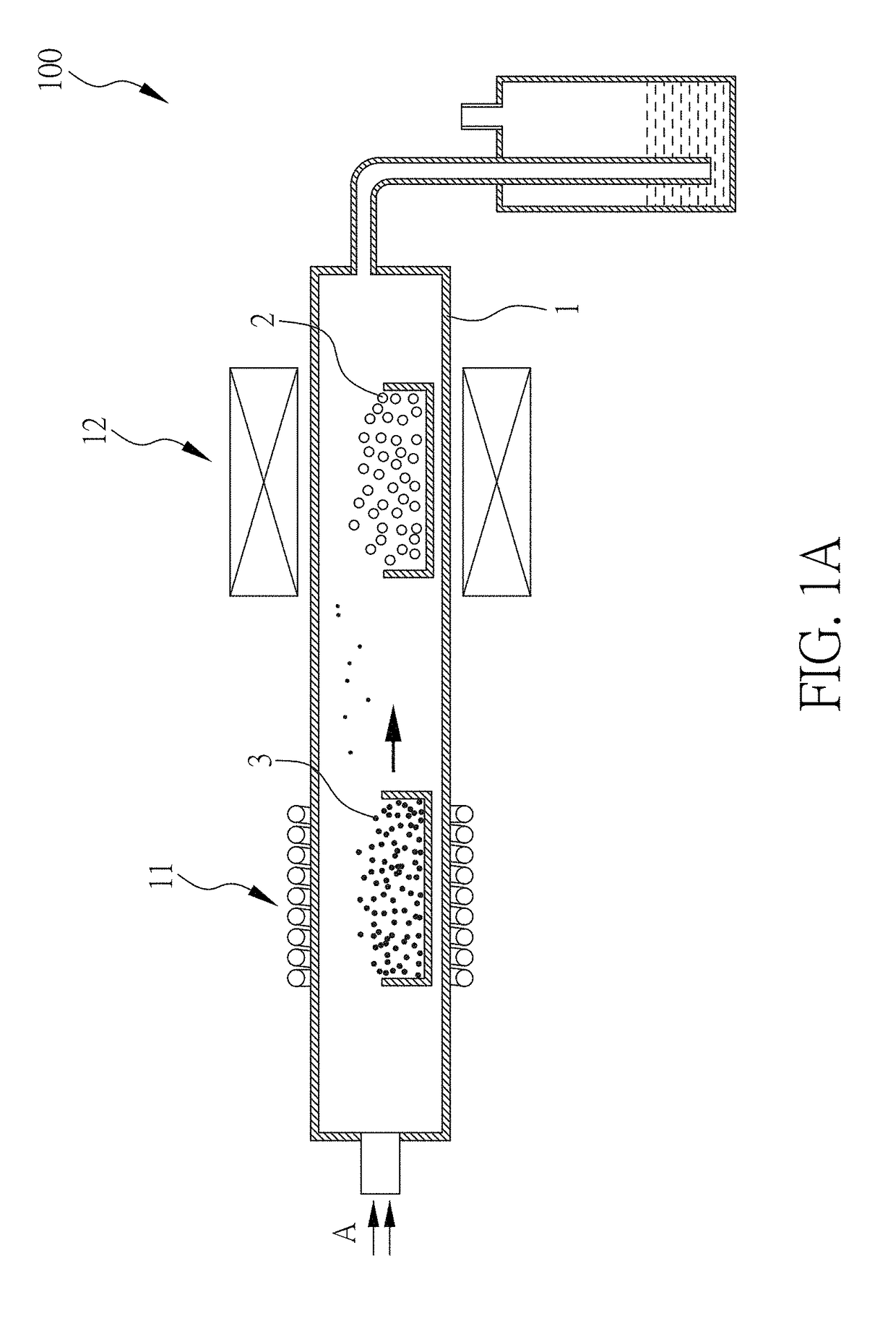
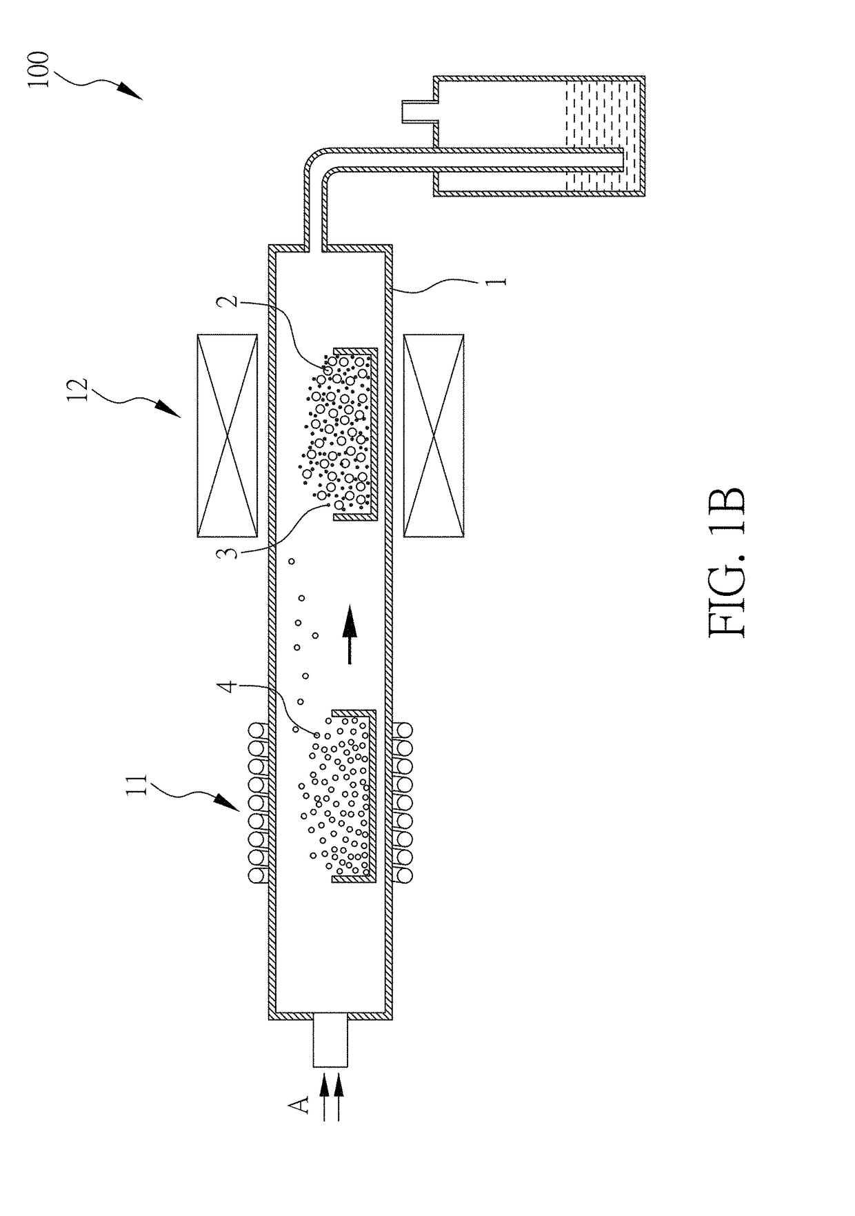
[0034]FIGS. 1A and 1B show manufacturing schemes according to the present embodiment. Silicon powder 2 (1.86 g) having a thickness of 100 nm and an average length or width of about 850 nm was placed in a chamber 1 of a second zone 12 of a thermal chemical vapor deposition system 100. Also, ferrocene 3 (3 g) used as an iron source was placed in a first zone 11 of the chamber 1. Thereafter, the chamber 1 was evacuated to high vacuum and backfilled with argon gas (600 sccm, 4 minutes) in a direction of gas flow A to remain the chamber 1 at 1 atm. The argon gas (600 sccm) was remained to flow into the chamber 1 in the direction of gas flow A. At the same time, a high temperature furnace was turned on to ensure the first zone 11 was heated to about 160° C. and the second zone 12 was heated to about 850° C. to decompose and vaporize ferrocene 3. The vaporized iron particles could permeate into gaps between silicon powders, and the deposition time was about 15 minut...

preparation example 2

osite Electrode Material

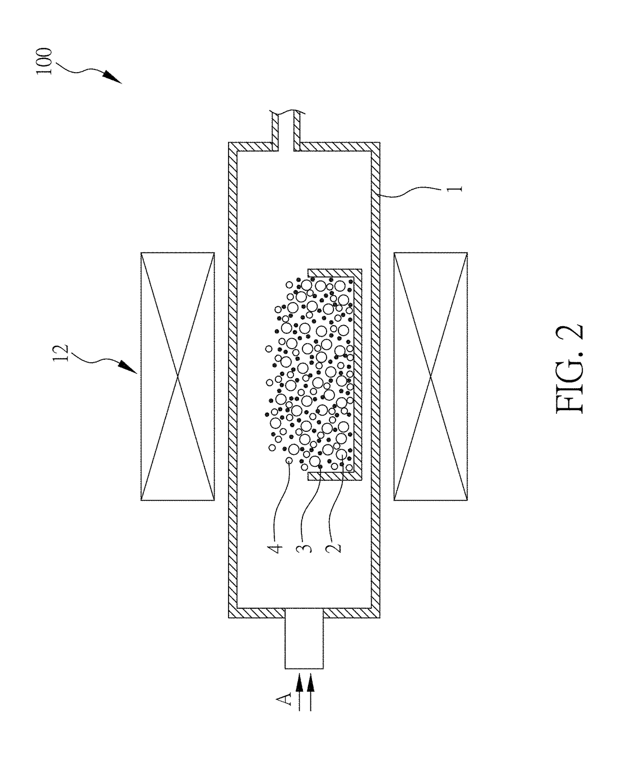
[0035]FIG. 2 shows a manufacturing scheme according to the present embodiment. Silicon powder 2 (1.86 g) having a thickness of 100 nm and an average length or width of about 850 nm, ferrocene 3 (3 g), and camphor 4 (13 g) were placed in a chamber 1 of a thermal chemical vapor deposition system 100. After the air in the chamber 1 was diluted to remove the air inside and the chamber 1 was backfilled with argon or nitrogen in a direction of gas flow A to about 1 atm pressure, the gas inlet and outlet of the chamber 1 were closed. Thereafter, a high temperature furnace was turned on to heat the chamber 1 to about 850° C. so as to vaporize ferrocene 3 and camphor 4. Both of the vaporized ferrocene and camphor were retained in the chamber 1. Furthermore, carbon nanotubes and carbon fibers grew on the silicon powder at the presence of Fe-based catalyst (i.e. ferrocene), and the deposition time was about 30 minutes. Then the high temperature furnace was turned off, a...

preparation example 3

osite Electrode

[0038]A composite electrode material according to the present invention, a conductive carbon black and an adhesive agent sodium carboxymethyl cellulose (NaCMC) were mixed at a weight ratio of 6:3:1. Then the mixture was added with deionized water, and stirred with a DC mixer to obtain a homogeneous active material. The homogeneous active material was placed in a vacuum chamber which was evacuated to a low pressure to remove internal bubbles of the homogeneous active material. Thereafter, a copper foil (10 μm) was provided and coated with 30 μm thick of the active material using a scraper to obtain an electrode. The coated electrode was placed in a vacuum oven, evacuated to vacuum, and baked at 65° C. for 8-12 hours to remove extra solvent. After cooling, the roll-press machine rolled and pressed the baked electrode to raise a packaging density of the electrode. Finally, the electrode was cut into a desired size. In one aspect of the present invention, the active mater...


PUM

PropertyMeasurementUnit
thicknessaaaaaaaaaa
widthaaaaaaaaaa
volume changeaaaaaaaaaa

Abstract

A novel composite electrode material and a method for manufacturing the same, a composite electrode containing said composite electrode material, and a Li-based battery comprising said composite electrode are disclosed. Herein, the composite electrode material of the present invention comprises: a core, wherein a material of the core is at least one selected from the group consisting of Sn, Sb, Si, Ge, C, and compounds thereof; and a carbon nanotube or a carbon fiber, wherein the carbon nanotube or the carbon fiber grows on a surface including a surface of the core.

Description

CROSS REFERENCE TO RELATED APPLICATION[0001]This application claims the benefits of the Taiwan Patent Application Serial Number 106129288, filed on Aug. 29, 2017, the subject matter of which is incorporated herein by reference.BACKGROUND OF THE INVENTION1. Field of the Invention[0002]The present invention relates to a composite electrode material and method for manufacturing the same.2. Description of Related Art[0003]Lithium ion battery is nowadays considered as one of the most efficient ways to store energy due to its high working voltage, high energy density, high battery power, long storage lifespan, and repeated charging / discharging. At present, graphite is the most commonly used commercial anode material for Li-ion battery, and the theoretical charge storage capacity value is about 372 mAhg−1. A solid electrolyte interphase (SEI) will be formed on the surface after the first charge of the battery resulting in an irreversible capacity loss. Hence, the actual capacity value is l...

Claims


Application Information

Patent Timeline
Patent Type & Authority Applications(United States)
IPC IPC(8): H01M4/1393H01M10/0525C23C16/26C01B32/168
CPCH01M4/1393H01M10/0525C23C16/26C01B32/168G01J3/44H01M2004/027H01M4/387H01M4/386B82Y30/00H01M4/366H01M4/38H01M4/625H01M2004/021C01B32/16C23C16/4418H01M4/1395H01M4/0428H01M4/587Y02E60/10
Inventor TZENG, YON-HUACHEN, WAI-LEONGHUANG, WEI-CHIH
Owner NAT CHENG KUNG UNIV
Why Eureka
Try Eureka