LED lamp with actively cooled heat sink

a technology of led lamps and heat sinks, which is applied in the direction of lighting and heating apparatus, semiconductor devices for light sources, and support devices for lighting and heating. it can solve the problems of generating a large amount of heat, reducing the quality of light, and reducing the heat emitted. the effect of heat reduction

Inactive Publication Date: 2011-07-14
MEDINIS DAVID M
View PDF8 Cites 34 Cited by
  • Summary
  • Abstract
  • Description
  • Claims
  • Application Information

AI Technical Summary

Benefits of technology

[0005]The primary object of the present invention is to provide a LED lamp with an actively cooled heat sink that reduces heat emitted by the LED lamp.

Problems solved by technology

However, these types of light bulbs use an excessive amount of electricity, generate a great deal of heat and do not provide a high quality light.
However, LEDs still generate an excessive amount of heat that can shorten the life of the LEDs, cause fatigue to medical workers and dry out exposed tissue.
Such LEDs typically generate so much heat that a heat sink is required to cool the lamps.
A problem with current heat sinks is that such are only passively cooled, which does not provide enough heat dissipation.
Another problem with current surgical lamps having LEDs is that the LEDs are typically mounted to an aluminum substrate board which causes an excess of heat to build on the aluminum substrate board around the LEDs, thereby resulting in damage to and a shorter life span of the LEDs.
Therefore, a need exists for an actively cooled heat sink for a LED lamp that efficiently dissipates the heat created by the LEDs and a non-conductive substrate that acts as an insulating layer between the heat sink and LEDs mounted in the lamp, thereby prolonging the life of the LEDs and decreasing the amount of heat generated by the LED lamp.

Method used


Image

  • LED lamp with actively cooled heat sink
  • LED lamp with actively cooled heat sink
  • LED lamp with actively cooled heat sink

Examples


Embodiment Construction

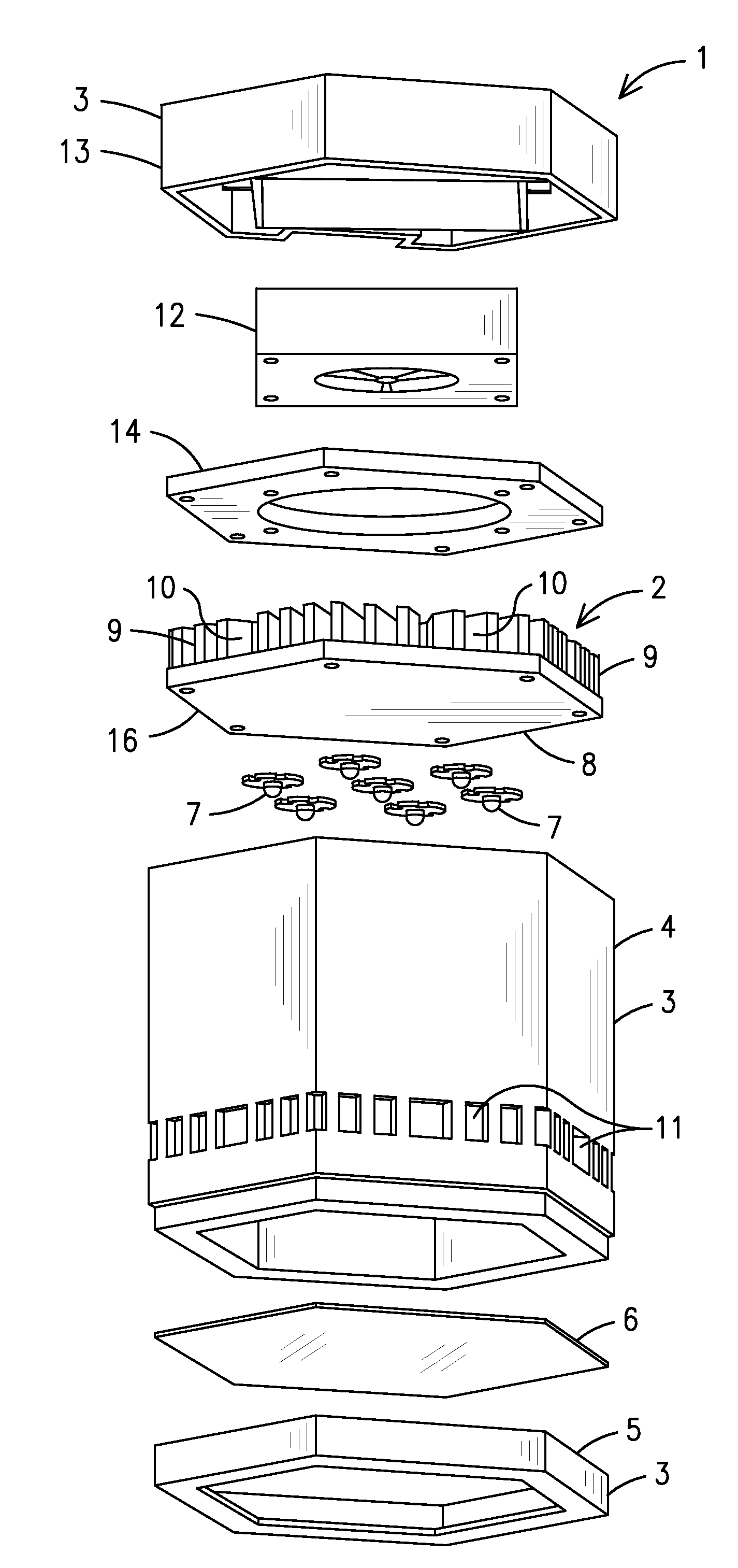
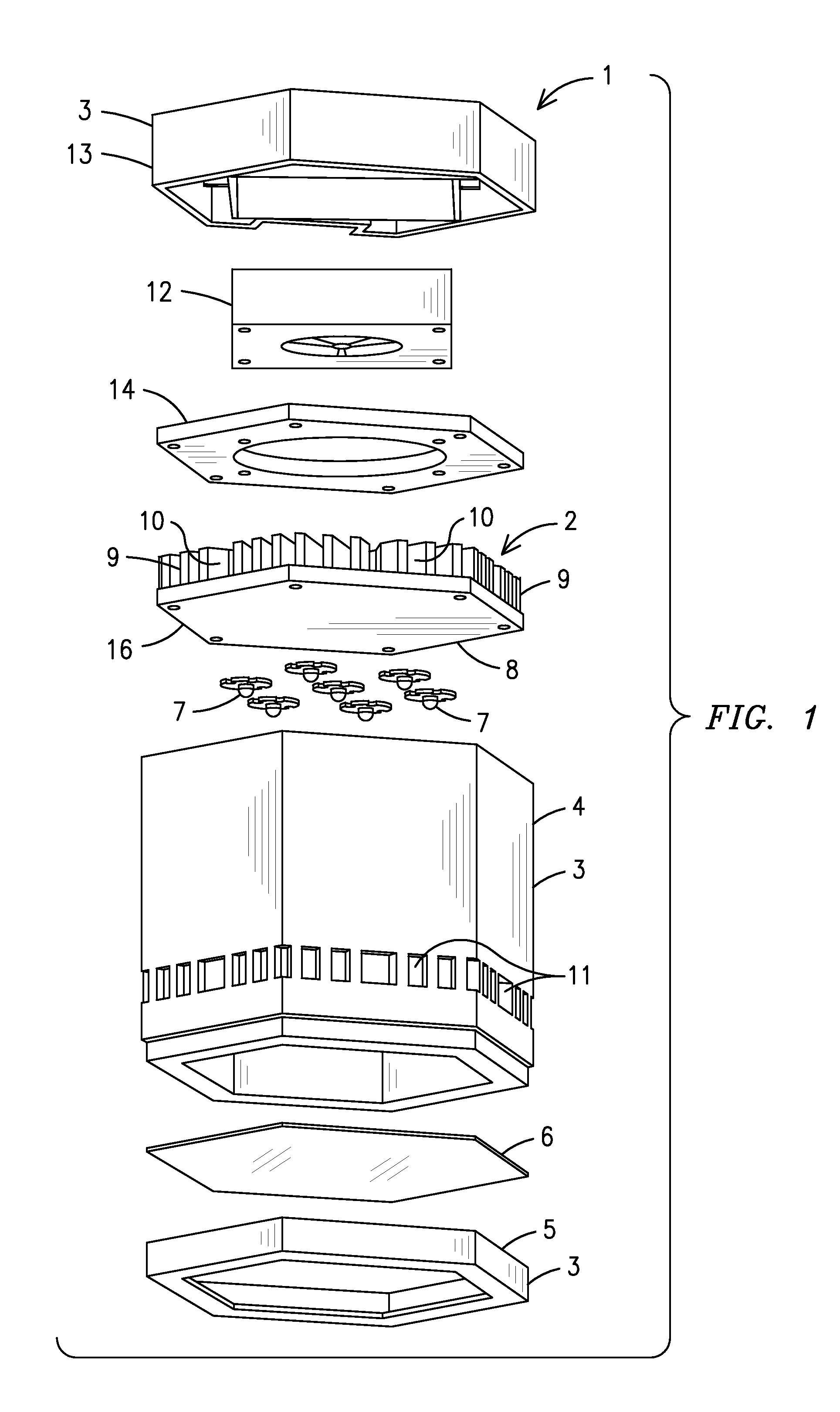
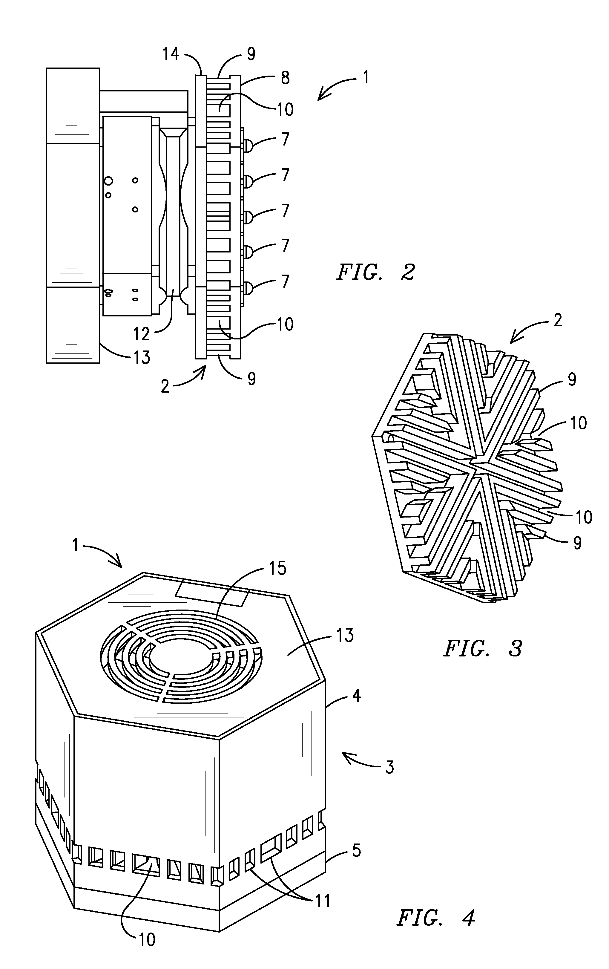
[0018]For purposes of describing the preferred embodiment, the terminology used in reference to the numbered accessories in the drawings is as follows:[0019]1. LED lamp[0020]2. heat sink[0021]3. housing[0022]4. main housing[0023]5. lens housing[0024]6. lens[0025]7. light emitting diode (“LED”)[0026]8. non-conductive substrate[0027]9. cooling vanes[0028]10. cooling channels[0029]11. air inlets[0030]12. fan[0031]13. rear housing[0032]14. exhaust outlet[0033]15. exhaust vent[0034]16. Flame Retardant 4 substrate (“FR4”)

[0035]With reference primarily to FIG. 1 and remaining drawing FIGS. as necessary, an exploded view of a LED 1 lamp with an actively cooled heat sink 2 of the present invention is shown. The LED lamp 1 and actively cooled heat sink 2 are housed in a housing 3 having a main housing 4, a lens housing 5 and a rear housing 13. The lens housing 5 houses a lens 6 on one end of the main housing 4. At least one light emitting diode (“LED”) 7 is mounted in a non-conductive substra...


PUM


Abstract

A LED lamp (1) with an actively cooled heat sink having at least one LED (7) mounted in a non-conductive substrate (8) that is attached to a heat sink (2) having a plurality of cooling vanes (9) extending therefrom. Heat generated by the at least one LED travels through the heat sink and then through the cooling vanes. Cooling channels (10) located between the cooling vanes allow for air flow between the cooling vanes. A plurality of air inlets (11) located in a housing (3) allow for air flow into the cooling channels. A fan (12) located in the housing pulls air through the air inlets through the cooling channels and across the cooling vanes through an exhaust outlet (14) where the fan then blows the air through exhaust vents (15) located on a rear of the housing.

Description

BACKGROUND OF THE INVENTION[0001]This invention relates to light emitting diode (“LED”) lamps, more particularly, a light emitting diode (“LED”) lamp that is compact in size and emits very little heat through the use of an actively cooled heat sink and a non-conductive substrate that acts as an insulating layer between the heat sink and LEDs mounted in the lamp.[0002]LED lamps are commonly used in operating rooms and examination rooms by doctors, surgeons, dentists and other medical personnel to illuminate work areas. Traditional surgical lamps consist of a housing having a reflector and one or more halogen or xenon light bulbs mounted therein. However, these types of light bulbs use an excessive amount of electricity, generate a great deal of heat and do not provide a high quality light. More recent surgical lamps use LEDs in an attempt to overcome these problems. However, LEDs still generate an excessive amount of heat that can shorten the life of the LEDs, cause fatigue to medica...

Claims


Application Information

Patent Timeline
Patent Type & Authority Applications(United States)
IPC IPC(8): F21V5/00F21S4/00
CPCF21K9/00F21V29/02F21W2131/202F21W2131/205F21V29/83F21V29/677F21V29/75F21V29/76F21V29/77F21Y2101/02F21Y2105/10F21Y2115/10F21V29/507F21V29/74
Inventor MEDINIS, DAVID M.
Owner MEDINIS DAVID M
Why Eureka
Try Eureka