Clip

a technology of a clip and a handle is applied in the field of clips, which can solve the problems of deterioration of work efficiency, cumbersome handling of pins and grommets in a state,

Active Publication Date: 2011-07-14
NIFCO INC
View PDF14 Cites 19 Cited by
  • Summary
  • Abstract
  • Description
  • Claims
  • Application Information

AI Technical Summary

Problems solved by technology

It is cumbersome to handle a pin and a grommet in a state as they are molded.
Even though such work of temporary fixing by an automatic assembly machine is efficient, if any misalignment between the pin and the grommet or displacement and / or shifting of the insertion position of the pin's dropping-out prevention protrusion with respect to the slits of the leg member on the side of the grommet occurs, it prevents the temporary fixing of the pin, damages the dropping-out prevention protrusion or stops the automatic assembly machine, thus giving rise to deterioration in work efficiency.

Method used


Image

  • Clip
  • Clip
  • Clip

Examples


Embodiment Construction

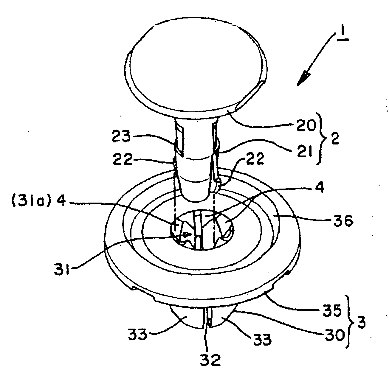
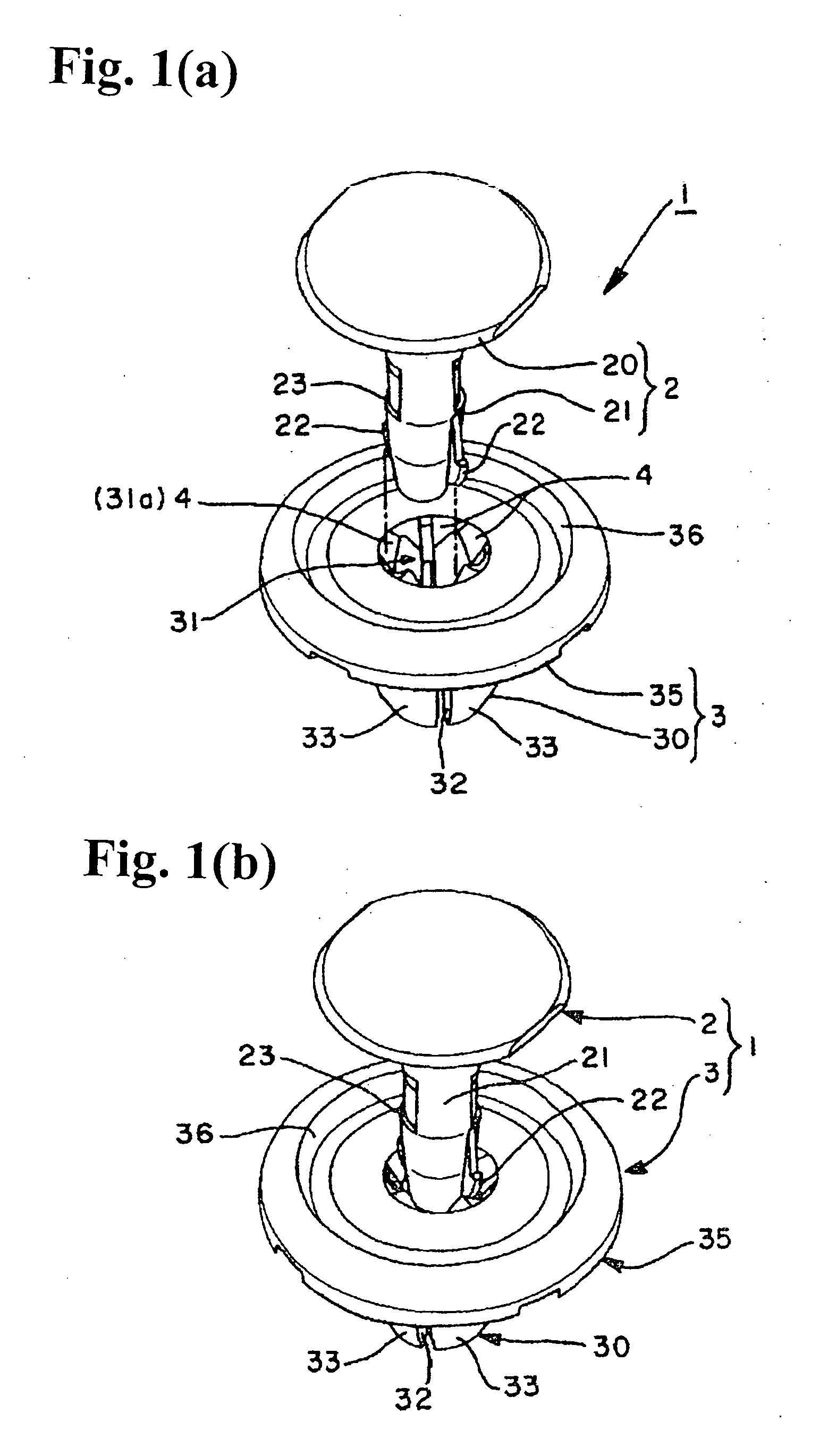
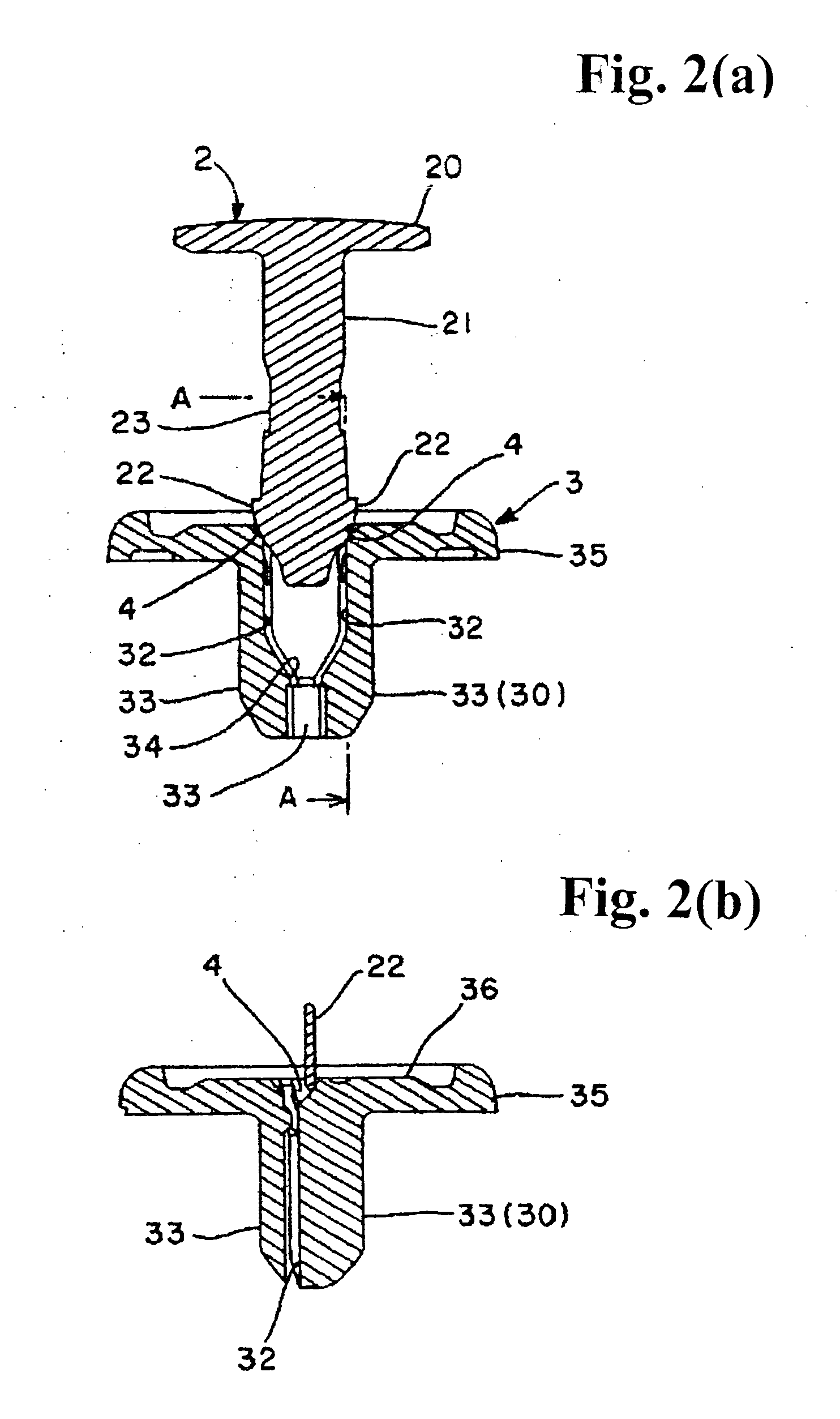
Now, optimal embodiments for carrying out the invention are described herewith reference to the drawings. The following description is made in details in the order of the drawings, from FIG. 1(a)-FIG. 7(d) concerning the clip configuration, and actuations to FIGS. 8(a)-8(d) and FIGS. 9(a) and 9(b) each concerning a modified example respectively. In FIG. 4(a), the pin corresponds to the cross section view looking in the direction of the arrow F-F of FIG. 7(c), and the grommet corresponds to the cross section view looking in the direction of the arrow B-B of FIG. 5(a). In FIG. 4(b), the pin corresponds to the cross section view looking in the direction of the arrow G-G of FIG. 7(d) and the grommet corresponds to the cross section view looking in the direction of the arrow C-C of FIG. 5(a). In the grommet of FIGS. 6(a) and 6(b), FIG. 6(a) corresponds to the cross section view looking in the direction of the arrow C-C of FIG. 5(a), and FIG. 6(b) corresponds to the cross section view loo...


PUM


Abstract

A clip includes a pin having at at least a part thereof a noncircular cross-section, and a grommet having an insertion hole into which the pin can be inserted, wherein a part of the grommet is adapted to be expandable by insertion of the pin into the insertion hole. The grommet has slope surfaces provided at an entrance-side hole edge of the insertion hole to lead the pin into the insertion hole when the pin is displaced from a normal position to be in contact with the entrance-side hole edge of the insertion hole.

Description

FIELD OF THE INVENTIONThe present invention relates to a clip comprising a grommet and a pin, in particular, to a type of clip, wherein the insertion position of the pin into the insertion hole of the grommet is controlled by the pin's temporary fixing or permanent fixing structure.DESCRIPTION OF THE RELATED ARTAs disclosed in Patent Reference 1, a clip of the invention comprises a pin having at at least a part thereof a noncircular cross-section, and a grommet having an insertion hole into which the pin can be inserted, wherein a part of the grommet is adapted to be expandable by insertion of the pin into the insertion hole, to become the clip in a state of permanent fixing. More specifically, the pin is provided with a head, an axis formed integrally below said head and a rib, i.e. dropping-out prevention protrusion and dropping out prevention piece, formed as protruding from a part of said axis. The grommet is provided with an approximately tubular leg member forming the insertio...

Claims


Application Information

Patent Timeline
Patent Type & Authority Applications(United States)
IPC IPC(8): F16B19/06
CPCF16B19/1081F16B2/20F16B2/00
Inventor WATANABE, YASUHIRO
Owner NIFCO INC
Why Eureka
Try Eureka