Orthopaedic device for correcting deformities of long bones

a technology for orthopaedic devices and long bones, which is applied in the field of orthopaedic devices for correcting deformities of long bones, can solve the problems of large overall bulk of orthopaedic devices, unresolved drawbacks, and limited use possibilities along the entire extension of longitudinal bars, so as to ensure maximum stability in rotation, reduce bulk, and reduce the effect of angular displacemen

Active Publication Date: 2011-07-14
ORTHOFIX SRL
View PDF16 Cites 38 Cited by
  • Summary
  • Abstract
  • Description
  • Claims
  • Application Information

AI Technical Summary

Benefits of technology

[0017]A further advantage of the invention is also the fact that the rotary coupling between the at least partially cylindrical surface of the male element and the corresponding female seat, where such an element is loosely received, makes it possible to obtain a wide angular displacement excursion, and at the same time allowing the clamp and the relative base to be positioned in any position along the longitudinal bar.
[0018]Moreover, such a coupling makes it possible to have an orthopaedic device that overall is compact and of minimal bulk.
[0019]A further advantage of the rotary coupling with cylindrical male element and relative female seat directly between the first clamp and the support base is the possibility of developing a wide assortment of interchangeable embodiments, with different rotary couplings, depending on requirements and the bone deformities to be corrected.
[0020]In particular, in a first embodiment, the orthopaedic device is configured so that the rotation axis is perpendicular to a plane that passes through the longitudinal bar and the osseous screws, to allow an adjustment of the angular position on said plane of the first group of osseous screws going towards or away from the bone, in relation to the other group of osseous screws.
[0021]In such a first embodiment, preferably, the first clamp comprises a cylindrical projection with axis coinciding with the rotation axis, which therefore acts as the male element, which is received in a circular hole that is formed in the support base,
[0022]Preferably, the support base and the first clamp have a substantially rectangular shape with respective long sides and short sides, and the cylindrical projection and the circular hole extend with maximum possible diameter between the two opposite long sides of the lower jaw, and of the support base, so as to ensure maximum stability in rotation.

Problems solved by technology

The known orthopaedic device, whilst advantageous from various points of view, and substantially meeting the purpose, does however involve drawbacks that have not yet been overcome.
The main drawback of the known orthopaedic device is the fact that the first angularly moveable clamp can only be arranged at an end of the guiding bar, thus offering a limited possibility of use along the entire extension of the longitudinal bar.
A further drawback of the known orthopaedic device is the fact that the angularly moveable clamp gives the orthopaedic device large overall bulk, to the detriment of its practicality and comfort of use by a patient.

Method used


Image

  • Orthopaedic device for correcting deformities of long bones
  • Orthopaedic device for correcting deformities of long bones
  • Orthopaedic device for correcting deformities of long bones

Examples


first embodiment

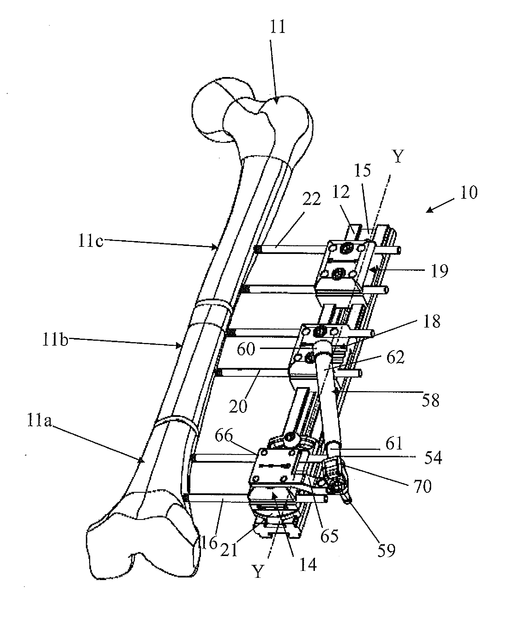
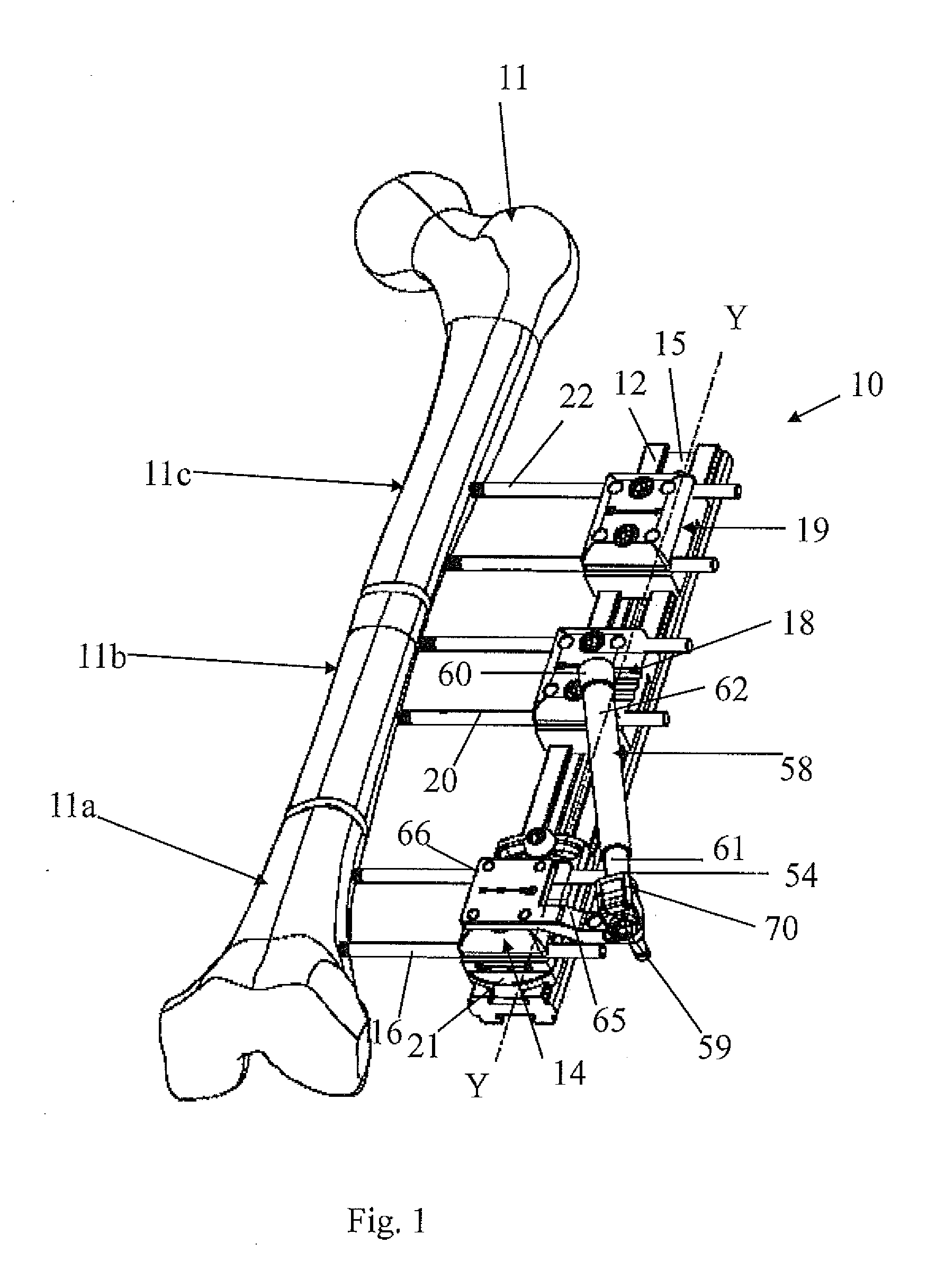
[0088]In particular, FIGS. 1 to 13 refer to an orthopaedic device 10 in accordance with a

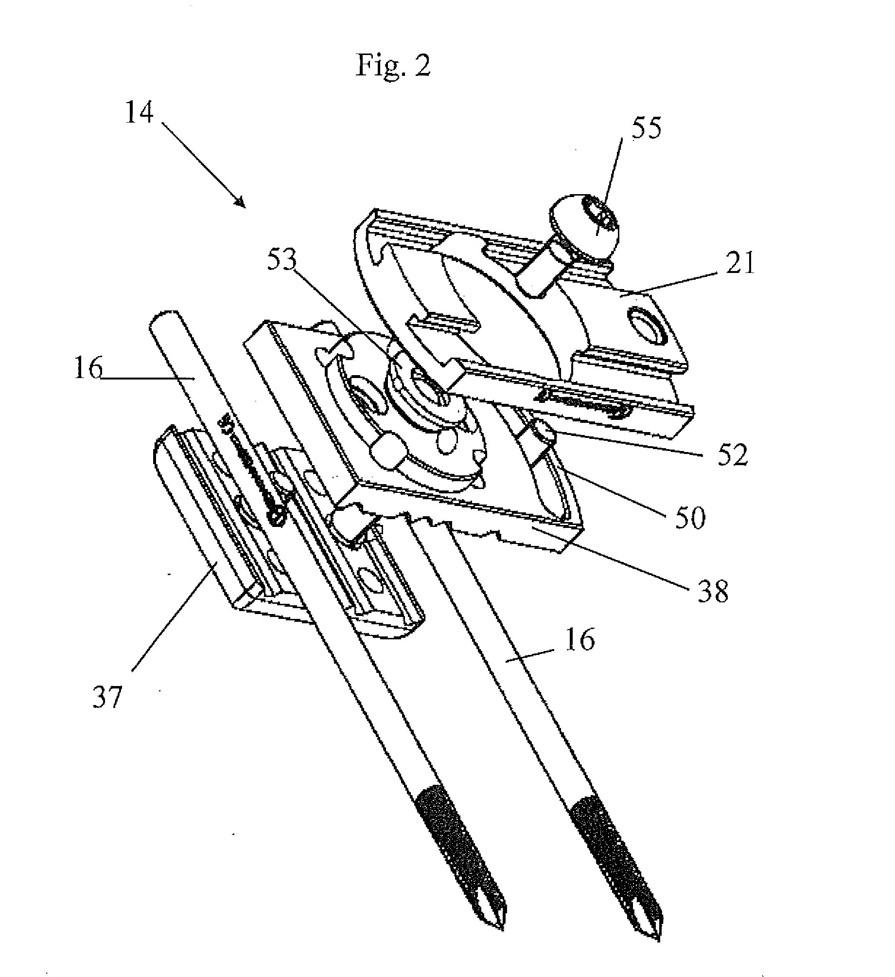
[0089]Such an orthopaedic device 10 comprises a bar 12, which we shall also define hereafter as longitudinal bar and which is made, for example, with synthesis materials like: Orthtek WF®, pultruded with carbon fibre in epoxy resin, or Peek CA30®. The bar 12 can also be made, for example, from aluminium alloy. Such a bar 12 extends along a given axis Y-Y, and is intended to be placed laterally and substantially parallel to the bone 11. The orthopaedic device according to the invention also comprises at least one first clamp 14 for a first group of osseous screws 16 screwed into a first piece 11a of the bone and a second clamp 18 for a second group of osseous screws 20 screwed into a second piece 11b of the bone. These clamps can also be made from Peek CA30® with steel, titanium alloy or aluminium alloy inserts.

[0090]In the example of FIG. 1, the orthopaedic device 10 also comprises a third clamp...

third embodiment

[0176]With reference to FIGS. 24 to 34 an orthopaedic device 210 in accordance with a third embodiment is now illustrated.

[0177]In such figures, components that are the same and those that have the same function already described keep the same reference numerals. Such shared components are therefore not described again in detail.

[0178]The orthopaedic device 210 comprises a first clamp 214 for a first group of screws 16 and a second clamp 18 for a second group of screws 20, removably mounted on the longitudinal bar 12.

[0179]The second clamp 18 and the longitudinal bar 12 are the same as those described earlier in the first embodiment.

[0180]The first clamp 214 is mounted onboard a support base 221, and is both angularly movable by means of rotary coupling and linearly translatable in relation to the support base 221. The support base 221 is fixed to the longitudinal bar by means of a locking screw 222.

[0181]In other words, in the orthopaedic device 221, by means of a single clamp 214 ...

second embodiment

[0191]Each driving screw 272 has substantially the same structure as the driving screws 152 described in the second embodiment, and therefore comprises a head, a shank, and a gorge arranged between head and shank.

[0192]Also in this embodiment, to axially hold each driving screw 272, to allow it to rotate but not translate, the orthopaedic device 210 comprises elastic stop pins 280, 281 which are inserted into the vertical appendices 260, 261 of the support base 221 from the bottom, in other words from the side of the support base 221 facing towards the longitudinal bar 12, to the sides of each driving screw 272, and received in the gorge of the screw, as illustrated in FIG. 31.

[0193]The operation of the orthopaedic device 210 is the following.

[0194]The first clamp 214 is slidingly housed onboard the support base 221, in particular in the recess 250, and connected to the support base 221 by means of the driving screws 272.

[0195]The support base 221 is fixed in a given position on the...


PUM


Abstract

Orthopaedic device (10, 110, 210, 310) for correcting deformities of a long bone (11), comprising a bar (12), extended along an axis (Y-Y) and intended to be placed alongside the bone (11), at least a first clamp (14, 214, 314) for a first group of osseous screws (16) and a second clamp (18, 19, 118) for a second group of osseous screws (20, 22), removably mounted on said bar (12), wherein the first of said clamps (14, 214, 314) is placed onboard a support base (21, 221, 321) in turn mounted on said bar (12), and angularly movable in relation to the support base around a given rotation axis (X-X, X′-X′, Z-Z) by means of a rotary coupling, characterised in that said rotary coupling comprises a male element (35; 235, 236, 237, 238, 239; 333, 334) associated with the first clamp (14, 214, 314) and having a surface at least partially cylindrical, and a corresponding female element (36; 130; 250, 254, 255; 336, 337) associated with the support base (21, 221, 321) and having a surface at least partially cylindrical constituting a seat for the loose coupling of the male element (35; 235, 236, 237, 238, 239; 333, 334).

Description

FIELD OF APPLICATION[0001]The present invention refers to an orthopaedic device for correcting deformities of long bones.[0002]The device is of the type comprising a longitudinal bar extending along a given axis, able to be positioned outside of the bone, and at least a first clamp for a first group of osseous screws, and a second clamp for a second group of osseous screws, respectively, in which said clamps are removably mounted on said longitudinal bar and in which the first of said clamps is placed onboard a support base, in turn mounted on said longitudinal bar and it is angularly movable by means of a rotary coupling around a given rotation axis in relation to the longitudinal bar.PRIOR ART[0003]In order to correct some deformities of a long bone it is known to use the technique of subjecting the bone to osteotomy forming two or more pieces, and positioning the two pieces in contact with one another in a correct position to allow the formation of fibrocartilage callus.[0004]It ...

Claims


Application Information

Patent Timeline
Patent Type & Authority Applications(United States)
IPC IPC(8): A61B17/00
CPCA61B17/6483A61B2017/00398A61B17/66
Inventor BAGNASCO, MARAVENTURINI, DANIELEMARINI, GRAZIANO
Owner ORTHOFIX SRL
Why Eureka
Try Eureka