
System and method for performing spinal surgery

Active Publication Date: 2011-07-14
K2M
View PDF22 Cites 107 Cited by
  • Summary
  • Abstract
  • Description
  • Claims
  • Application Information

AI Technical Summary

Benefits of technology

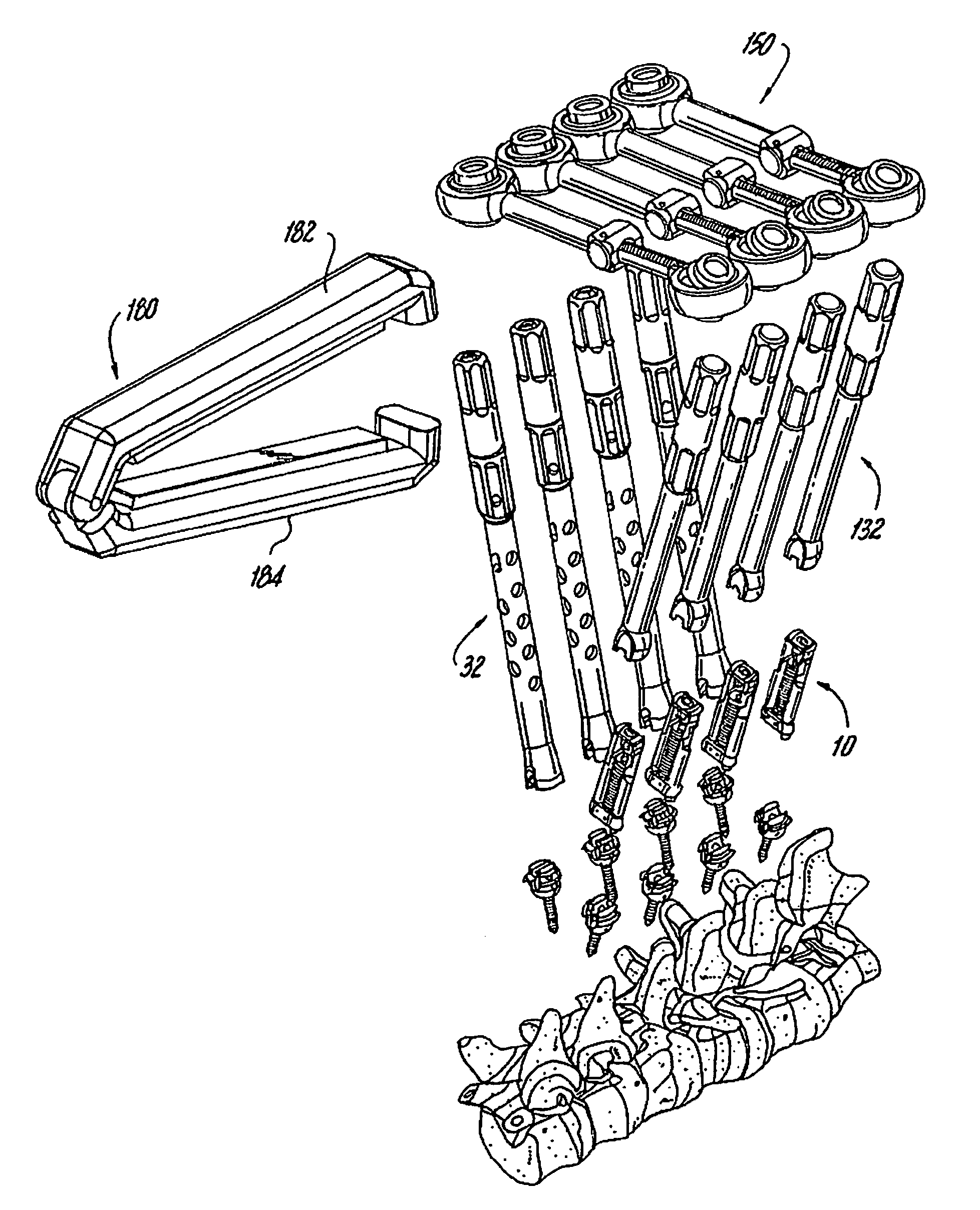
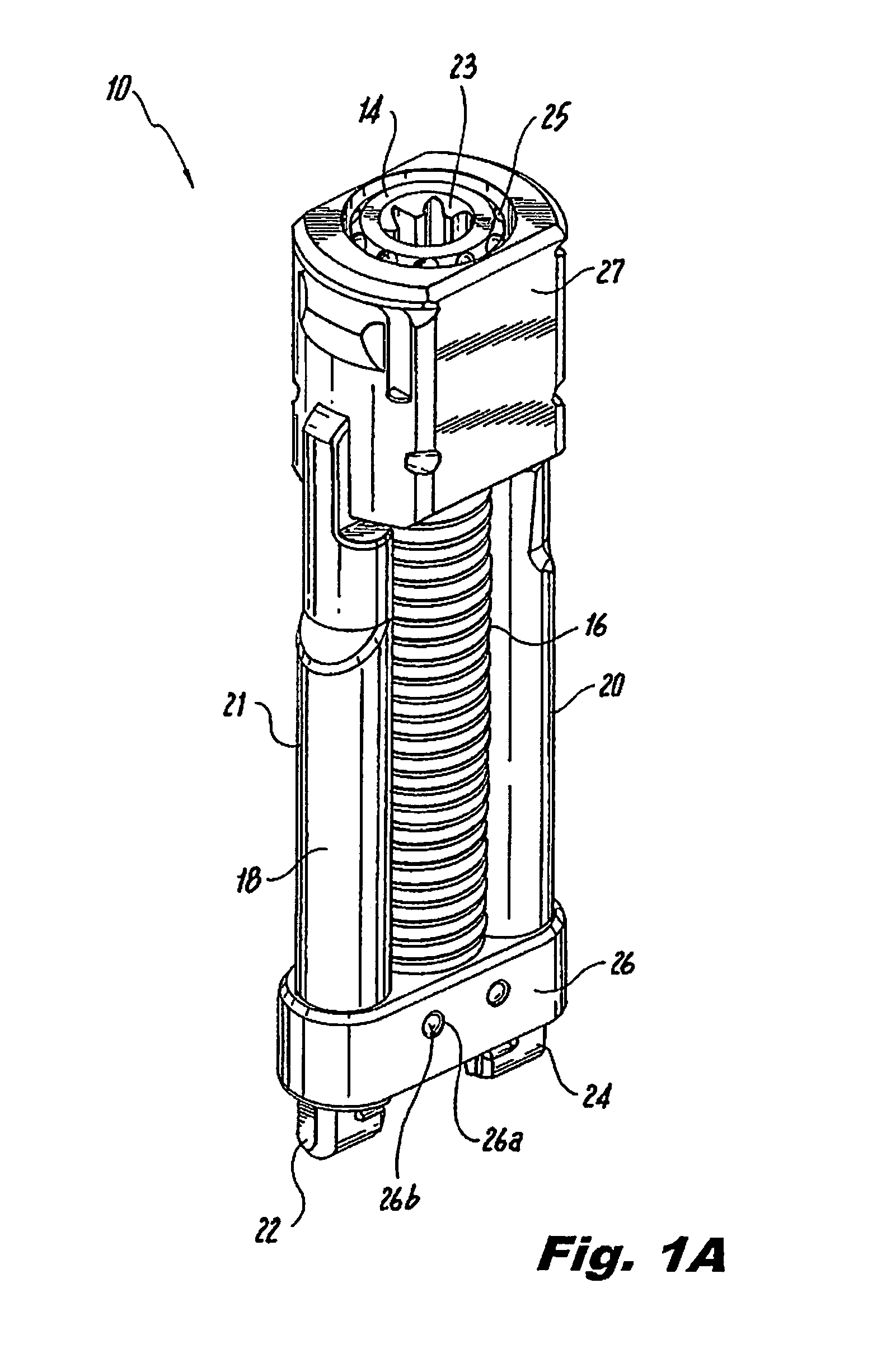
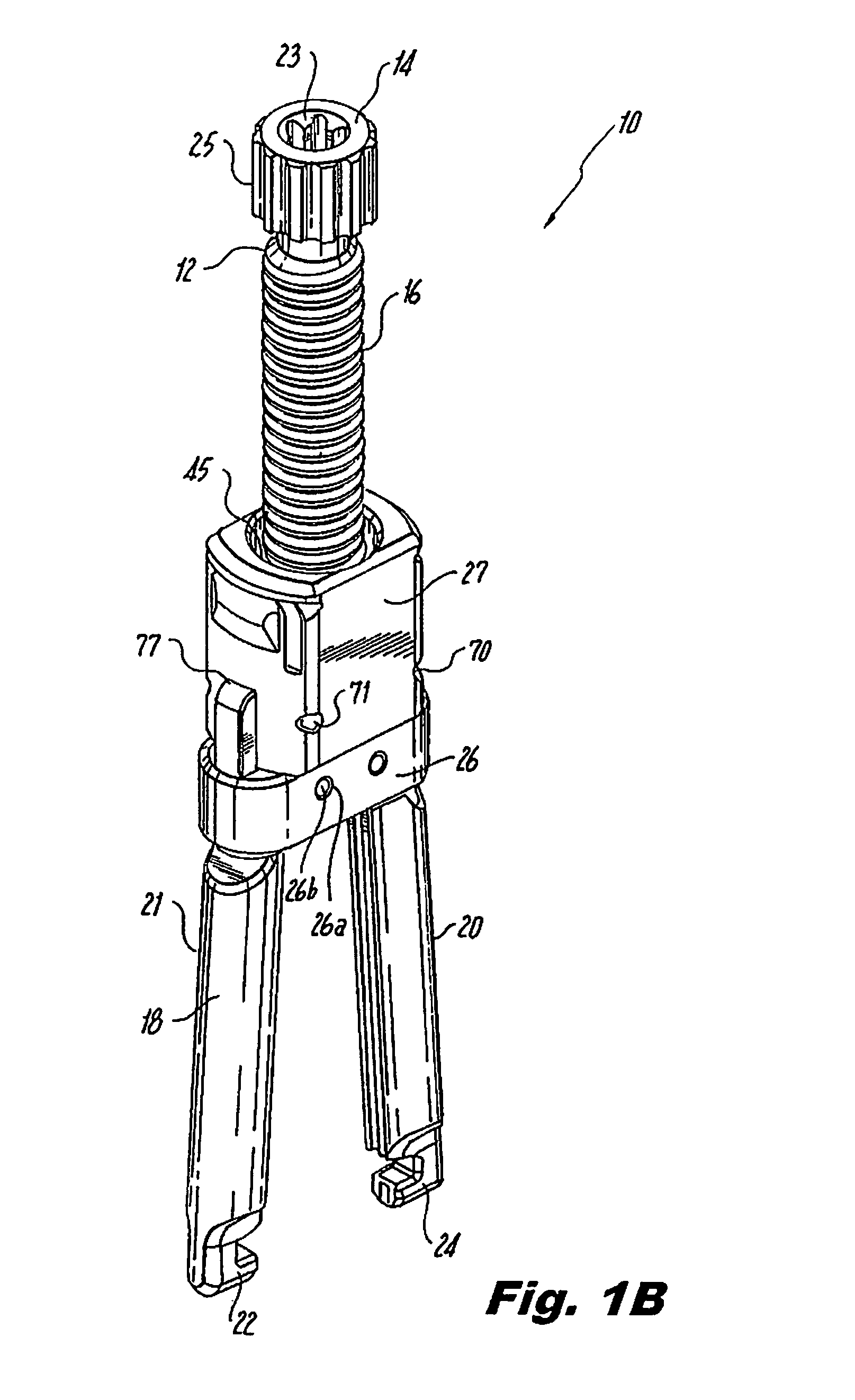
[0011]In any of the disclosed systems or methods, the spinal rods may be pre-bent in a physiological sagittal plane prior to attachment of the vertebrae using bone screws. A rod reduction device having taper lock screw connecting mechanisms and a rod reduction screw jack mechanism can be used to facilitate rod reduction and spinal rotation corrections in a single step. The screw jack mechanism rod reduction devices may be attached to bone screws on the concave side of the deformity and manipulators may be attached to bone screws on the convex side of the deformity to facilitate rod reduction and spinal rotation in a single action. In general, the disclosed methods include the steps of implanting a plurality of bone screws into multiple bores of the spine using taper lock bone screws, and more particularly utilizing multiplanar taper lock screws including, inter alfa, multiplanar taper lock screws, uniaxial taper lock screws, and monomial taper lock screws. Taper lock screws provide the ability to partially lock the screw, permitting further or continued manipulation of the spine while holding position while partially locked prior to fully locking. Prior to connecting the spinal rods, the spinal column may be manually manipulated to reduce the deformity.
[0014]Taper lock screws may used in one portion of the spinal construct and set screw or nut style screws are used in another portion of the spinal construct. Also, in an embodiment of a method for conducting spinal surgery, a portion of a spinal rod is anchored to vertebrae on the spinal column using polyaxial screws while the remaining portion of the spinal rod is anchored to the vertebrae using uniplanar taper lock bone screws with the lowest instrumented vertebra (LIV) anchored to the spinal rods using monoaxial bone screws. Counter-torsion of the lowest instrumented vertebra may be accomplished. For example, a linked transverse coupler attached to the lowest instrumented vertebra will facilitate stabilization and provide counter torsion during correction.

Problems solved by technology

However, in other cases, the devices may subsequently be removed when no longer needed.
Such connections fail to provide any degree of flexibility during the surgical procedure, thereby inhibiting manipulation and repositioning of the spinal vertebrae prior to locking the connecting rods into a rigid connection with the bone screws.
However, polyaxial bone screws and other flexible connections may provide a range of motion that is too great in cases such as scoliosis.
Achieving proper alignment using conventional connecting rod and screw systems that fail to limit movement of a bone screw's head to a single plane or single axis of rotation may be problematic.
While a rigid bone screw may facilitate spinal manipulation, attachment of the connecting rods is more difficult using such devices.
Conventional surgical methods, however, are not designed to take full advantage of the employment of specialized bone screws, such as uniplanar and monoaxial bone screws.
Such a locking system does not facilitate partial locking of the screw to the rod so that the relative position of the rod and the screw will remain stabile as adjustments are made to the position of that screw and other screws along the rod prior to final locking, and throughout final locking of the construct.

Method used


Image

  • System and method for performing spinal surgery
  • System and method for performing spinal surgery
  • System and method for performing spinal surgery

Examples


Embodiment Construction

,

[0056]Embodiments of the presently disclosed apparatuses and methods for spinal surgery will now be described in detail with reference to the appended drawings, in which like reference numerals designate identical or corresponding elements in each of the several views. Throughout the following description, the term “proximal,” will refer to the end of a device or system that is closest to the operator, while the term “distal” will refer to the end of the device or system that is farthest from the operator. In addition, the term “cephalad” is used in this application to indicate a direction toward a patient's head, while the term “caudad” indicates a direction toward the patient's feet. Further still, for the purposes of this application, the term “medial” indicates a direction toward the middle of the body of the patient, i.e., away from the middle of the body of the patient. The term “posterior” indicates a direction toward the patient's back, while the term “anterior” indicates a...


PUM


Abstract

Systems and methods for surgical spinal correction are disclosed. A system including a plurality of bone screws, spinal rods, manipulators, and / or transverse couplers is disclosed for the manipulation of the spinal column is disclosed. A method of achieving, in a single action, manipulation and / or rotation of the spinal column using the disclosed system is disclosed. Also disclosed is a method of conducting spinal surgery to correct spinal deformities wherein spinal rods are pre-bent in a physiological sagittal plane prior to attachment of the vertebrae using bone screws.

Description

CROSS REFERENCE TO RELATED APPLICATIONS[0001]This application claims the benefit of U.S. Provisional Patent Application Ser. No. 61 / 104,411 filed Oct. 10, 2008, and U.S. Provisional Application Ser. No. 61 / 133,357 filed Jun. 27, 2008. The entire contents of each of these prior applications are incorporated by reference herein.BACKGROUND[0002]1. Technical Field[0003]The present disclosure relates to orthopedic surgery, and more particularly, to apparatuses and methods for surgical correction of spinal deformities.[0004]2. Background of Related Art[0005]Correction of a spinal deformity typically requires stabilization and fixation of vertebrae in a particular spatial relationship. Surgical spinal correction procedures involve the placement of a plurality of bone pins, anchors, cables, hooks, or screws placed in adjacent vertebrae and using spinal rods to maintain a predetermined spatial relationship between the vertebrae. Such devices may be permanently implanted in the subject. Howev...

Claims


Application Information

Patent Timeline
IPC IPC(8): A61B17/70A61B17/88
CPCA61B17/7086A61B17/708A61B17/7076A61B17/7077A61B17/7079A61B17/7082A61B17/7083A61B17/7085
Inventor BOACHIE-ADJEI, OHENEBAROCK, ANDREW THOMASWOO, RAYMONDBARRUS, MICHAELJONES, SCOTT
Owner K2M
Learn More