[0009]Accordingly, the present invention has been made keeping in mind the above problems occurring in the prior art, and an object of the present invention is to provide an integrated
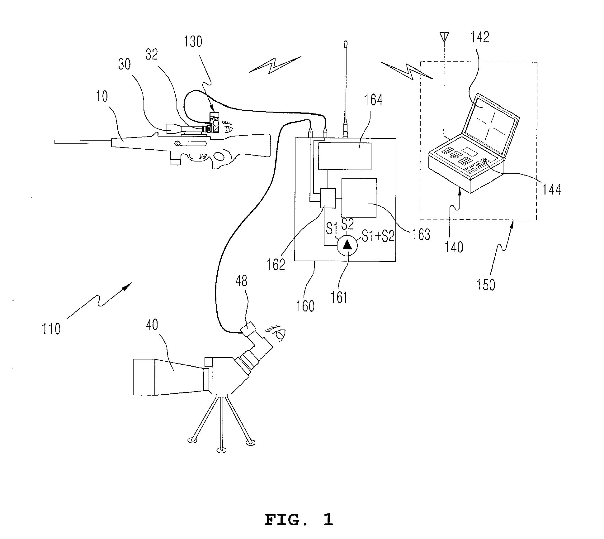
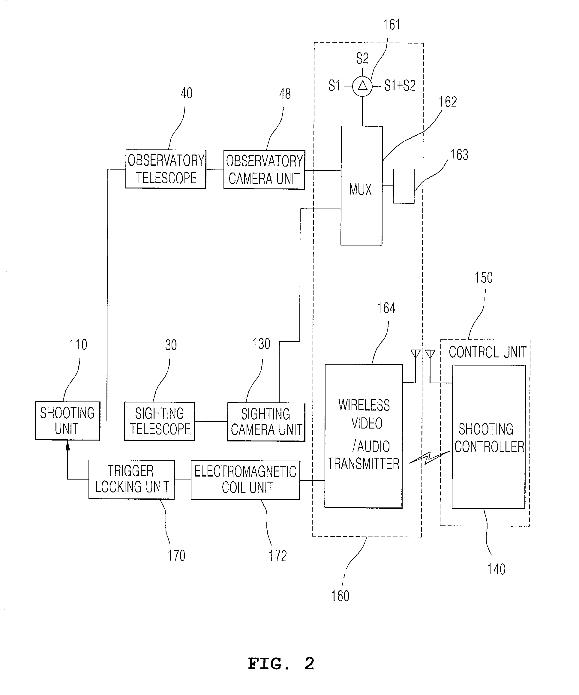
control system and method for controlling the aimed shooting of a sniper and the observation of a spotter, which form image signals corresponding to the same real-time moving images viewed by both a sniper who aims at a target with a firearm and will shoot at the target, and a spotter who widely grasps the safety of the place where the sniper is disposed and the surroundings of the target, and then observes a situation indicating whether the sniper has precisely hit the target at the time of shooting at the target while preventing the sniper's position from being leaked to the other party in such a way that image signals are formed by a sniper optical unit composed of an optical device and a camera which are attached to the outside of a sighting telescope mounted on the firearm of the sniper, and that image signals are formed by a spotter optical unit composed of an optical device and a camera which are attached to the outside of the
observatory telescope of the spotter, so that two types of video captured by the sniper and the spotter can be selectively transmitted by the sniper or spotter by manipulating the channel switches of a
wireless control transmission unit, and the video obtained by the two types of channels can be combined with each other using a
multiplexer and can be transmitted in real time to the shooting controller of a commanding office located at a remote place through the
wireless control transmission unit while the combined images are viewed on a small-sized monitor in a multi-screen division form, and which allows a commander in a commanding office to view the moving images so as to make a precise decision pertaining to shooting while sharing images of the spot in real time with the sniper and the spotter, and remotely controls shooting by controlling whether to release the trigger locking unit of the sniper's firearm at the remote place.
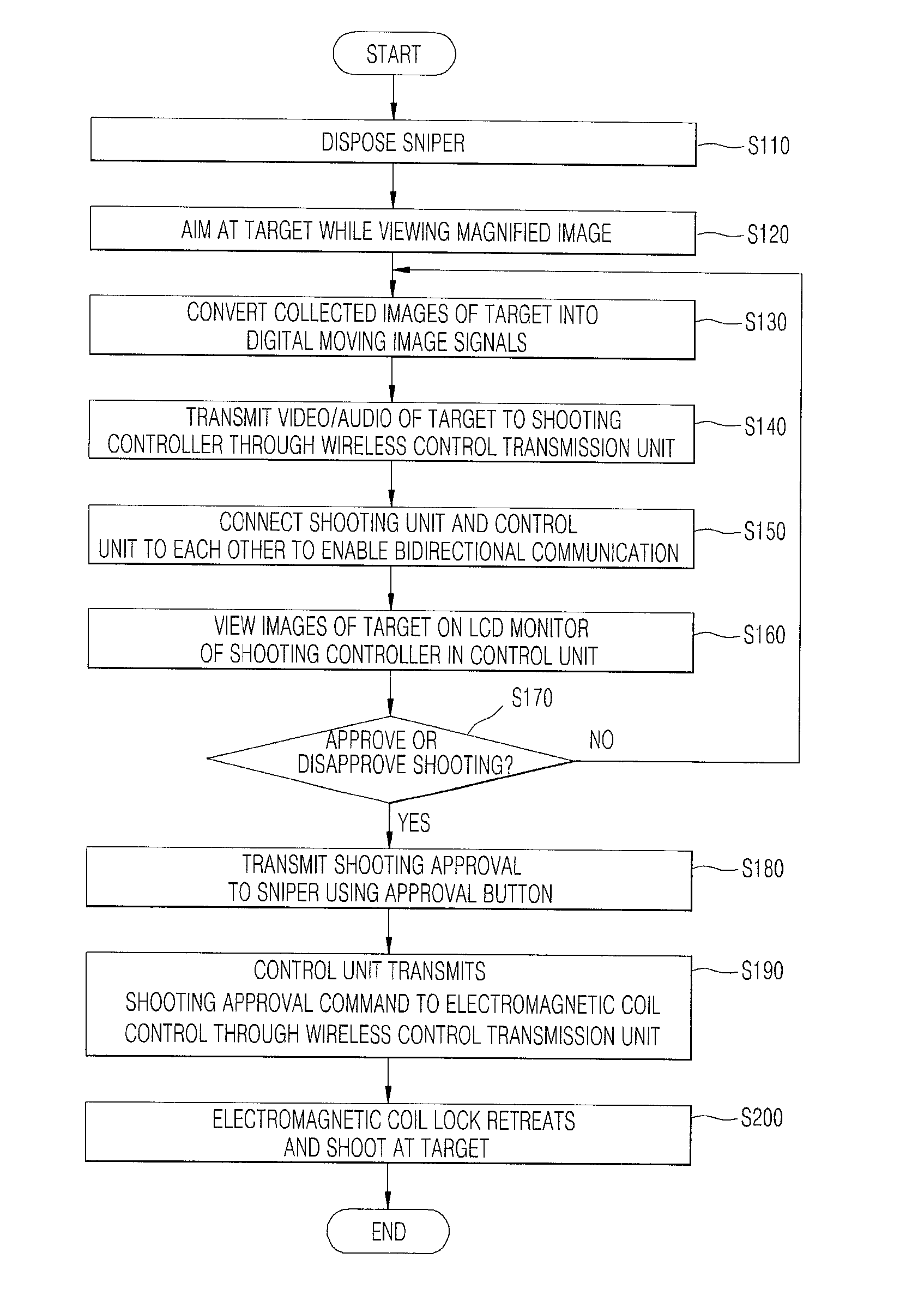
[0011]Further, the present invention provides an integrated control method of controlling aimed shooting of a sniper and observation of a spotter, comprising disposing a sniper who identifies a location of a target and will shoot at the target while aiming at the target with a firearm; allowing the sniper to aim at the target while viewing a magnified image of the target using a second
eyepiece of a sighting camera unit attached to a sighting telescope provided on the firearm; allowing the sniper to identify the target using the second
eyepiece and collect images of the target, transmitting part of the images of the target to a
camera lens through a first
prism of a reflection optical unit of the sighting camera unit, and allowing an
image conversion module to convert the images of the target into
digital video signals; locating the prism on a first side of a first
eyepiece of the sighting telescope by which the sniper identifies the target, receiving images of the target corresponding to part of light and deflecting the images at an angle of 90° using the prism, allowing the
camera lens to receive the images of the target, directly provided by the prism, allowing the
image conversion module to convert analog video into
digital video signals, and transmitting the digital moving video signals of the target to a shooting controller of a commanding office located at a remote place through a
wireless control transmission unit; connecting a shooting unit connected to the
wireless control transmission unit and a
control unit located at the remote place to each other so that images / sound and shooting control signals therebetween are bidirectionally communicated in real time; outputting the images of the target on a
Liquid Crystal Display (LCD) monitor of the shooting controller and enabling the images of the target to be viewed in real time by the
control unit; the
control unit determining whether to approve or disapprove shooting in such a way that a commander detects a precise location of the target and is aware of a time of shooting while viewing the images of the target on the LCD monitor of the shooting controller, and then transmitting a shooting approval
signal to the
wireless control transmission unit of the shooting unit; when the commander presses an approval button provided on a portion of the shooting controller, transmitting a shoot approval command to the sniper; when the control unit issues a shoot command, transmitting the shoot command to an electromagnetic control mounted on the firearm through the
wireless control transmission unit; and the electromagnetic control transmitting a radio release
signal in compliance with the shoot approval command, and retreating an
electromagnetic lock of a trigger locking unit from its locked position, so that the sniper views a turn-on operation of a release indication lamp and shoots at the target in a locking release state by pulling the trigger.

