
Prefabricated Wall Element

a prefabricated, wall element technology, applied in the direction of structural elements, ropes and cables for vehicles/pulleys, building components, etc., can solve the problems of difficult access to connecting plates, difficult use of prior art solutions, and difficulty in accessing connecting plates

Inactive Publication Date: 2011-07-21
B B BONELLI BUILDING
View PDF51 Cites 7 Cited by
  • Summary
  • Abstract
  • Description
  • Claims
  • Application Information

AI Technical Summary

Benefits of technology

[0004]However, the prior art solutions require a high resistance of the reinforced concrete to prevent local damages to the wall element due to loads transmitted by the ends of the reinforcement or by the connecting plates when laying the wall element. Thus, the prior art solutions are difficult to use with cement-wood prefabricated wall elements, in which a substantial portion of the inert material is constituted by wood fragments, and which has a resistance lower than that of concrete or conventional reinforced concrete.

Problems solved by technology

Thus, the prior art solutions are difficult to use with cement-wood prefabricated wall elements, in which a substantial portion of the inert material is constituted by wood fragments, and which has a resistance lower than that of concrete or conventional reinforced concrete.
A further disadvantage of the prior art wall elements consists in the difficult access to the connecting plates with the aim of assembling the connecting members, for example pins or bolts.
A further disadvantage of the prior art wall elements consists in the visibility of the connecting plates with the wall mounted and in the need to cover the connecting plates, and thus the entire wall, by means of a layer of plaster or any other coating material.

Method used


Image

  • Prefabricated Wall Element
  • Prefabricated Wall Element
  • Prefabricated Wall Element

Examples


Embodiment Construction

)

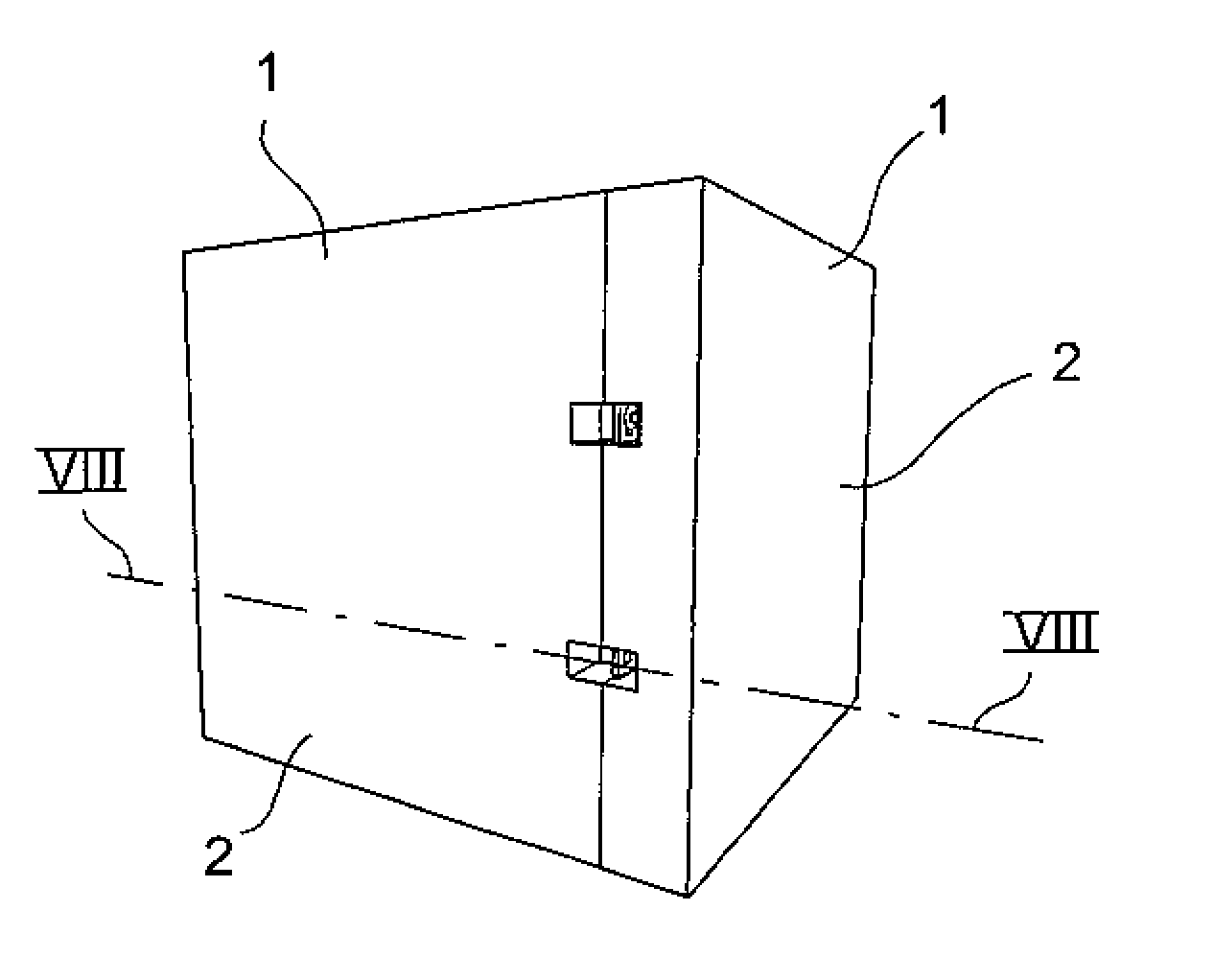
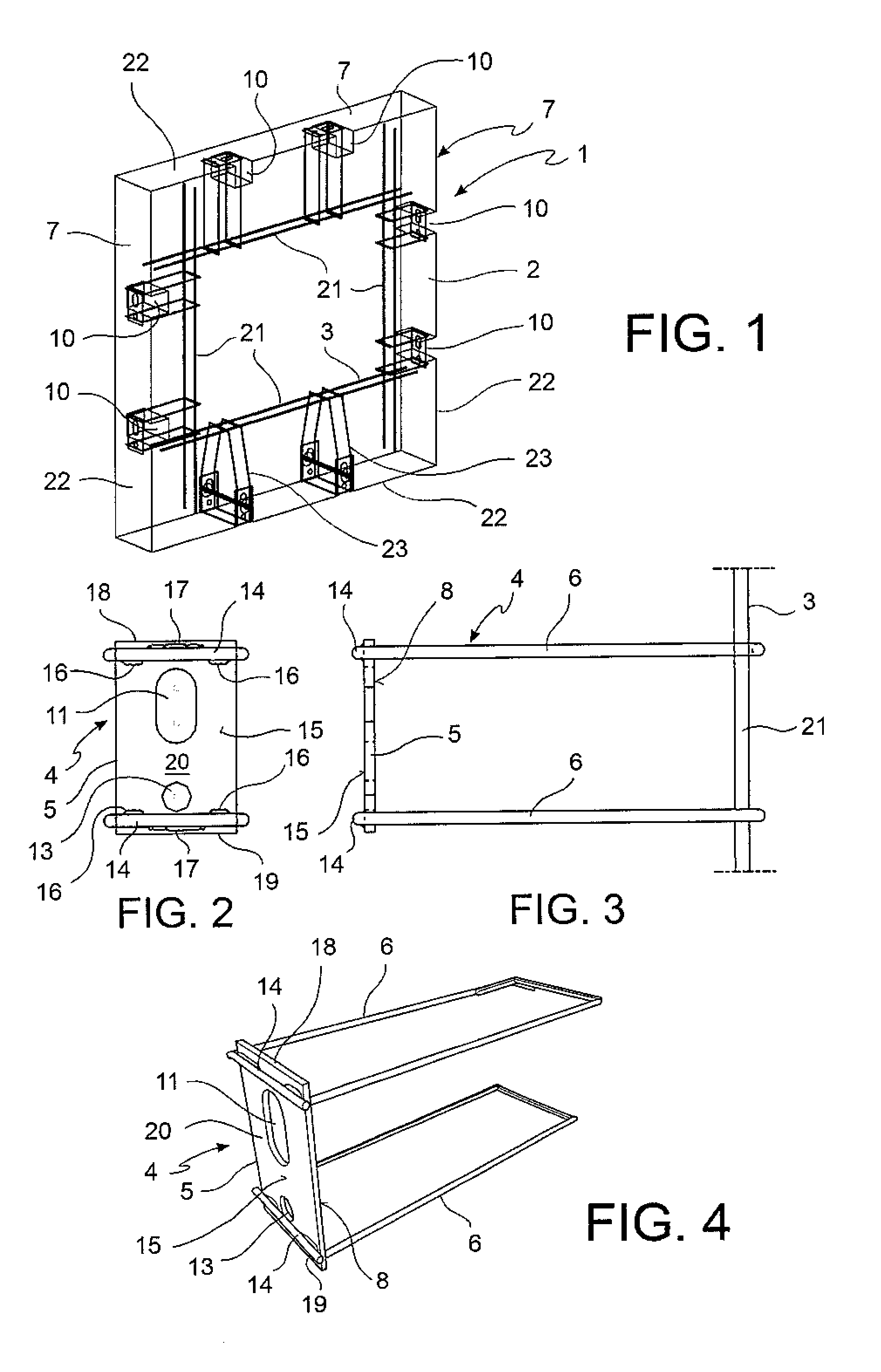
[0027]Referring to the figures, a prefabricated wall element is indicated in its entirety with reference number 1.

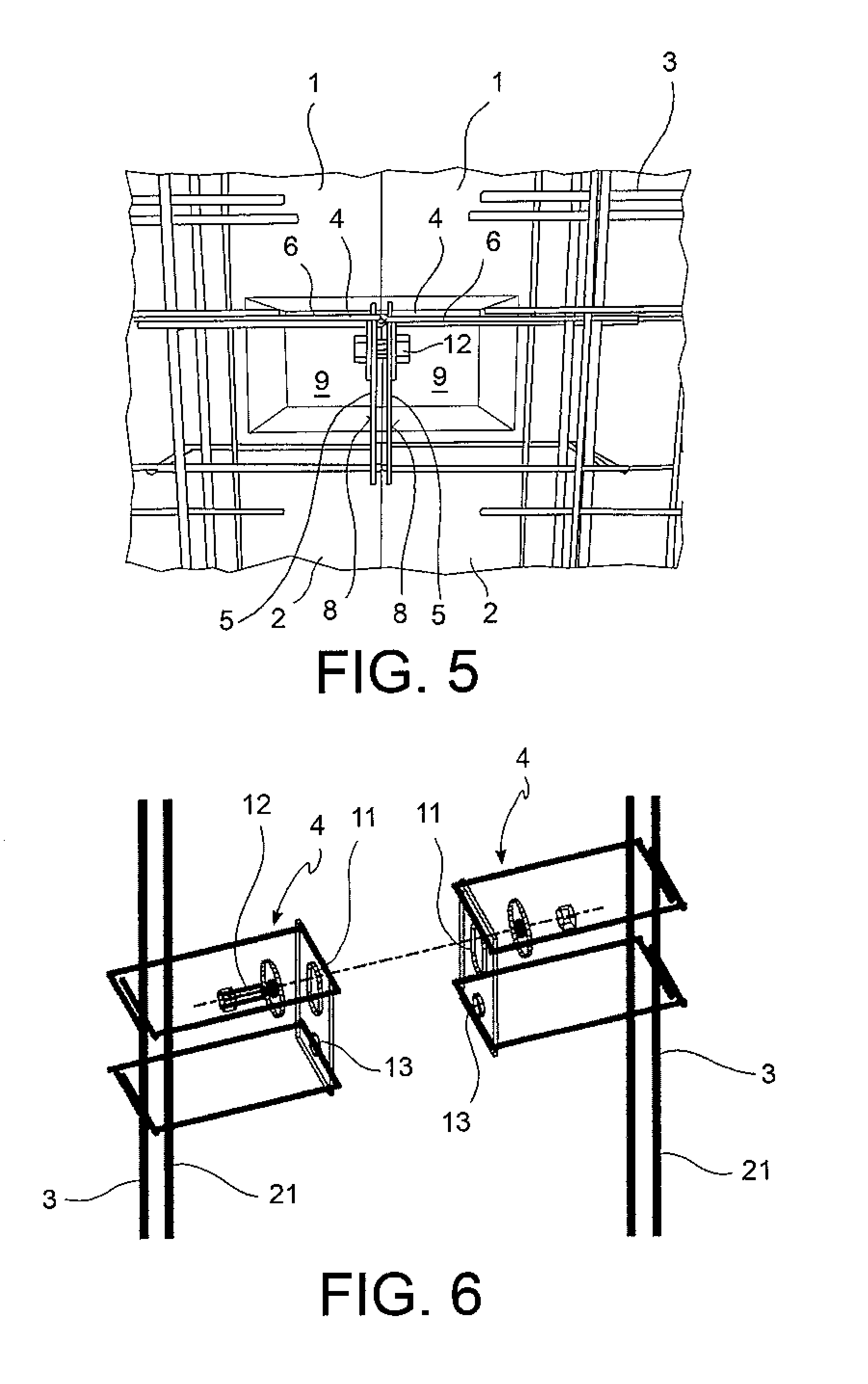
[0028]The element 1 comprises a cement-wood plate-like body 2, a metal reinforcement 3 embedded in the body 2, as well as means for positioning and connecting the wall element 1 with respect to further wall elements 1 and other structural elements, for example a ceiling or a floor.

[0029]The positioning and connection means comprise one or more plate-bracket units 4 with a connecting plate 5 rigidly connected to at least one, preferably at least two anchoring brackets 6, in which the connecting plate 5 is arranged in a connection surface 7 of the plate-like body 2 intended to face and adhere to a corresponding connection surface 7 of a further wall element 1 and the anchoring bracket / s 6 are embedded in the body 2 and engaged to the reinforcement 3. Furthermore, the plate-like body 2 together with a rear surface 8 of the connecting plate 5 facing inwards the plate-like b...


PUM


Abstract

A prefabricated wall element comprises a wood-cement plate-like body, a reinforcement embedded in the body and one or more plate-bracket units with a connecting plate rigidly connected to one or more anchoring brackets embedded in the plate-like body and engaged to the reinforcement, in which the plate-like body together with a rear surface of the connecting plate facing inwards the plate-like body define an assembling seat with an access opening lateral to the connecting plate.

Description

[0001]A wood-cement prefabricated wall element with means for mutual positioning and connection with other wall elements, ceilings and floors forms an object of the present invention.[0002]Reinforced concrete prefabricated wall elements, in which some ends of the reinforcement rids project from the edges of the wall element so as to be welded to corresponding projecting ends from other wall elements are known.[0003]Reinforced concrete prefabricated wall elements with steel connecting plates anchored into the cement of the wall element and provided with holes for receiving pins or bolts for connection to other wall elements or to ceilings or floors are also known.[0004]However, the prior art solutions require a high resistance of the reinforced concrete to prevent local damages to the wall element due to loads transmitted by the ends of the reinforcement or by the connecting plates when laying the wall element. Thus, the prior art solutions are difficult to use with cement-wood prefa...

Claims


Application Information

Patent Timeline
IPC IPC(8): E04B1/41
CPCE04B1/04Y10T403/5733E04G21/142E04B2001/4192
Inventor BONELLI, GIUSEPPE
Owner B B BONELLI BUILDING
Learn More