
Energy generating system using a plurality of waterwheels

Inactive Publication Date: 2011-07-21
MEADON SEAN BRIAN +1
View PDF8 Cites 20 Cited by
  • Summary
  • Abstract
  • Description
  • Claims
  • Application Information

AI Technical Summary

Benefits of technology

[0006]It is therefore an object of the present invention to provide an energy generating system using a plurality of waterwheels, with the system aiming to improve the efficiency of the waterwheels, whilst also reducing the loss of energy due to friction.SUMMARY OF THE INVENTION
[0016]In an example embodiment, the water scoops are connected together at their ends by a weighted outer rim to create a flywheel effect.

Problems solved by technology

Other types included undershot and breast waterwheels, but they were far less efficient.
These overshot waterwheels however, have a number of design flaws that resulted in vast volumes of water being wasted / spilled, and therefore making them relatively inefficient.
Thus, structurally, a turbine-based hydropower system is a once-off design that is very specific to a particular dam's arrangement, which is limiting.

Method used


Image

  • Energy generating system using a plurality of waterwheels
  • Energy generating system using a plurality of waterwheels
  • Energy generating system using a plurality of waterwheels

Examples


Embodiment Construction

[0026]This invention deals with the maximizing of power extracted from falling water, with the preferred embodiment below being described with reference to an overshot waterwheel. However, it is feasible that similar waterwheel configurations can use other types of waterwheels, and these are also included in the scope of this invention.

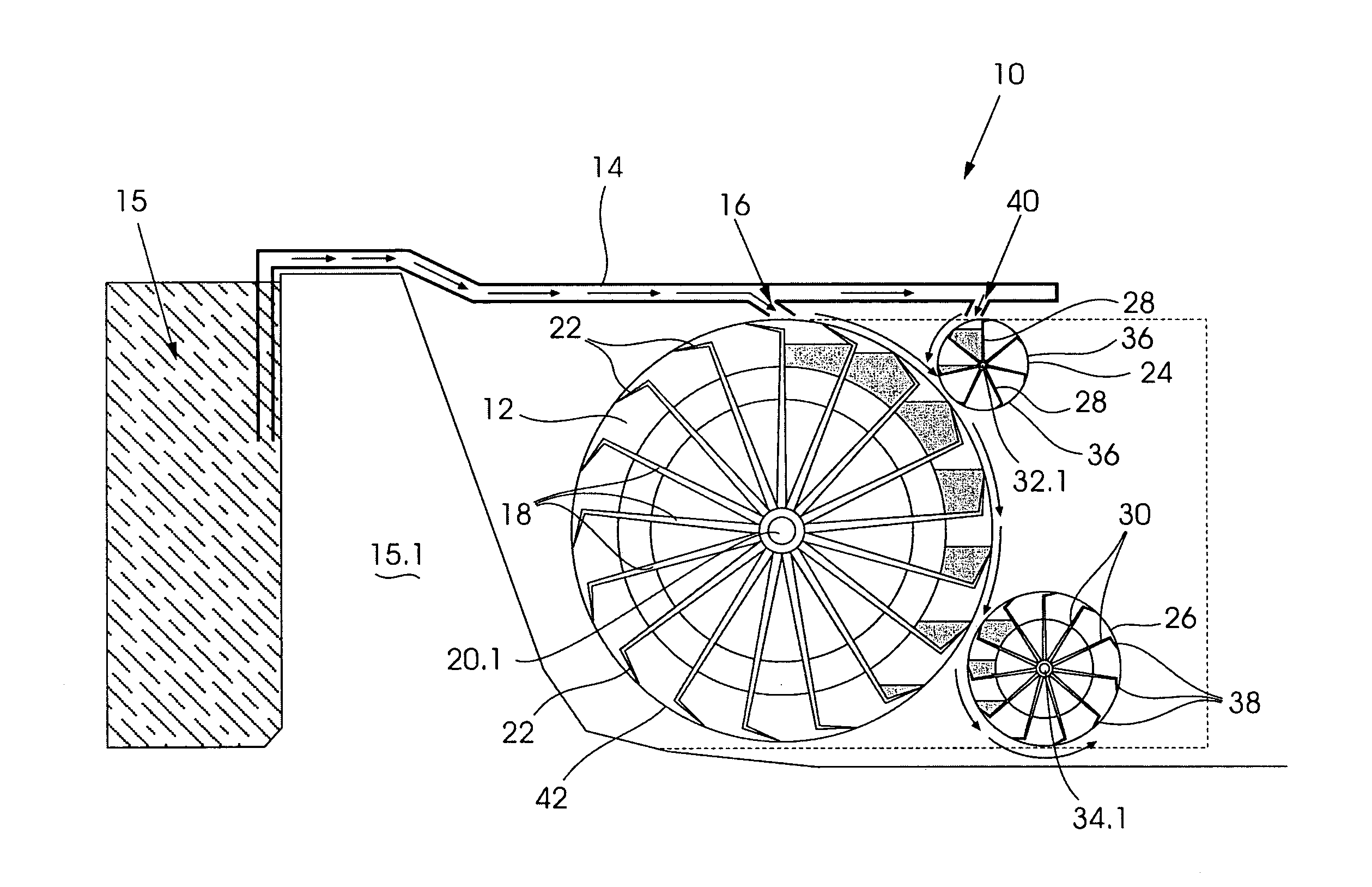
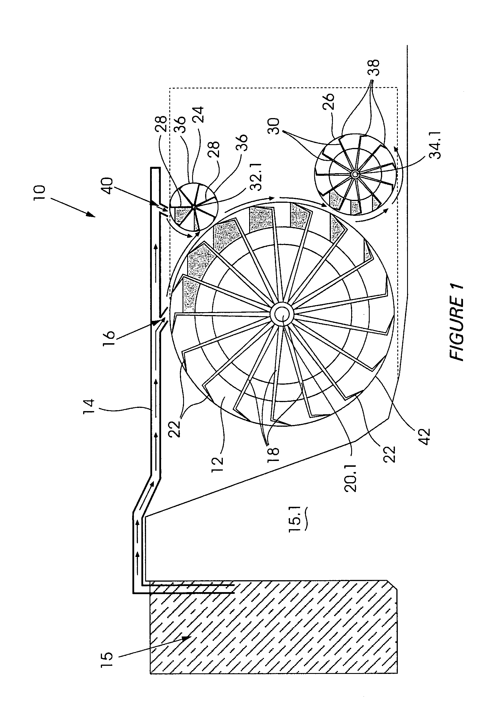
[0027]Referring first to FIGS. 1 to 3, an energy generating system 10 is shown comprising a primary waterwheel 12 for receiving water from a head penstock 14 having a first outlet 16 defined therein. The head penstock 14 is arranged to receive water from a dam 15 supported by a dam wall 15.1 in any one of a number of known ways. For example, although not shown, an upper pumping set may be provided to pump water into the penstock 14 for transport to the system 10.

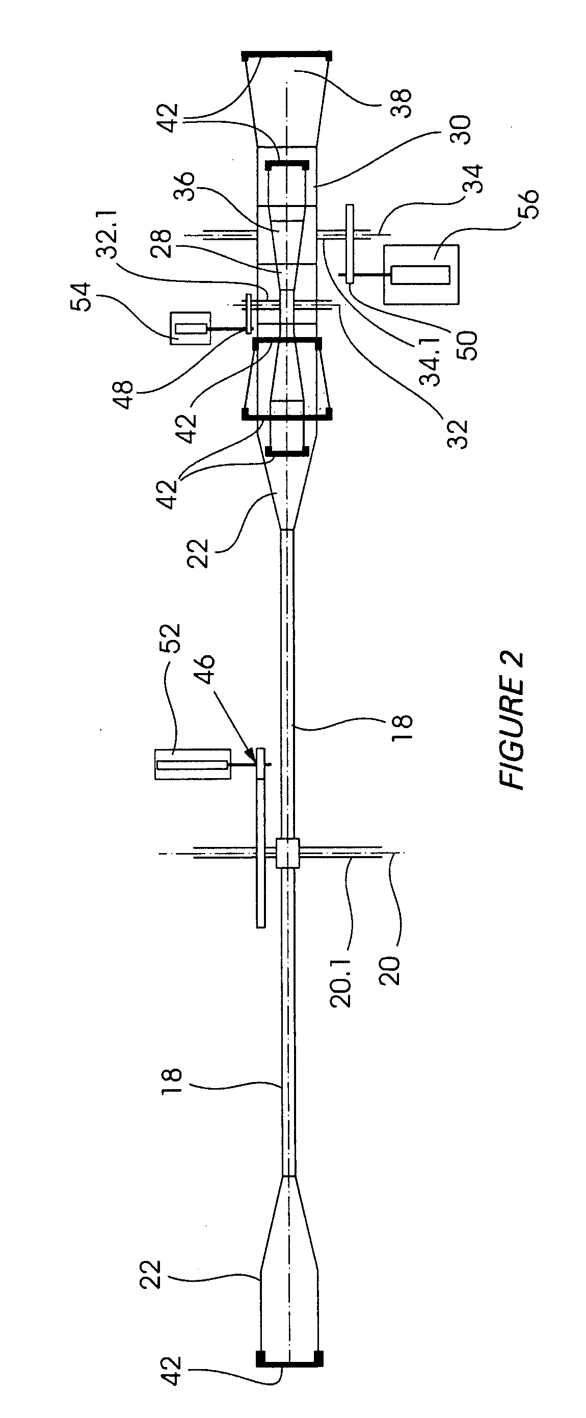
[0028]The primary waterwheel 12 comprises a plurality of radial arms 18 rotatable about a primary axis 20, the radial arms 18 terminating in water scoops 22 for accommodating the water from th...


PUM


Abstract

An energy generating system is provided, comprising a primary waterwheel for receiving water from a head penstock or upper pumping setup, the primary waterwheel comprising a plurality of radial arms rotatable about a primary axis, the radial arms terminating in water scoops for accommodating the water from the head penstock or upper pumping setup, the primary waterwheel defining head height. The system further comprises at least one additional waterwheel located within the head height of the primary waterwheel, the additional waterwheel also comprising a plurality of radial arms rotatable about an axis, the radial arms terminating in water scoops for accommodating either excess water from the head penstock or upper pumping setup or water that has spilled out of the water scoops of the primary waterwheel. In an example embodiment, the primary waterwheel and the at least one additional waterwheel are vertically orientated. In an example embodiment, the at least one additional waterwheel is smaller than the primary waterwheel.

Description

FIELD OF THE INVENTION[0001]This invention relates to an energy generating system using a plurality of waterwheels, and in particular, to the improvement of the generation of hydro-electric power by means of an integrated configuration of a plurality of waterwheels. This invention also refers to improvements in the general shape and construction of individual waterwheels with a view to increasing their efficiency in their generation of electrical energy from flowing water.BACKGROUND OF THE INVENTION[0002]A waterwheel is a hydropower machine which extracts power from the flow of water. The most efficient earliest waterwheels were so-called overshot waterwheels, and these comprised water scoops or buckets for receiving and temporarily holding water flowing over the waterwheel from an elevated head of water, which in turn caused the waterwheel to turn. Other types included undershot and breast waterwheels, but they were far less efficient. Overshot waterwheels have the advantage of not...

Claims


Application Information

Patent Timeline
IPC IPC(8): F03B7/00F03B13/08
CPCF03B7/003F03B11/00F03B13/06Y02E60/17Y02E10/223Y02E10/226Y02E10/22F05B2240/40Y02E10/20Y02E60/16
Inventor MEADON, SEAN BRIANMEADON, ANNE-MARIE
Owner MEADON SEAN BRIAN
Learn More