Method for operation of an HVAC system

a technology of hvac system and hvac system, which is applied in the direction of domestic cooling apparatus, vehicle heating/cooling device, vehicle components, etc., can solve the problems of unoptimized mixing of partial air mass flow, unsatisfactory heat loss of efficient internal combustion engine at low ambient temperature, other unintended effects, etc., to optimize the exergetic degree of utilization of hvac system, increase the range of vehicle, optimize the effect of energy demand

Active Publication Date: 2011-07-21
HANON SYST
View PDF16 Cites 70 Cited by
  • Summary
  • Abstract
  • Description
  • Claims
  • Application Information

AI Technical Summary

Benefits of technology

[0038]It is advantageous if the heating heat exchanger is established as cross-counterflow heat exchanger, thus as highly efficient heat exchanger that maximizes temperature gradients between the supplied and removed coolant mass flows.
[0048]The advantages of the method according to the invention can be summarized as follows: Only that heat is delivered to the HVAC system that is needed to air condition the passenger compartment; the heat is provided at the temperature level required for reaching or maintaining the comfort, thus optimizing the exergetic degree of utilization of the HVAC system; the energy demand of the HVAC system can be optimized by specific control of the heat, thereby significantly increasing the range of the vehicle; the stratification of the air mass flow in the air channel is independent of the operational state of the HVAC system. So the comfort of the passengers can be ensured at any point in time; the HVAC system is designable compact; and due to the operation only in two end positions, the temperature door can be actuated by a simple servo motor.

Problems solved by technology

The heat loss of efficient internal combustion engines is not sufficient at low ambient temperatures to heat a coolant to a temperature level required for comfortably heating the passenger compartment.
However, mixing of the partial air mass flows is not optimum.
Depending on the kind of the heat exchanger, undesired thermal stratifications over the surface of the heating heat exchanger may result.
In addition, the discontinuities of the coolant mass flow due to varying engine speeds produce other unintended effects.
Further, in coolant side-controlled systems the varying coolant mass flow, as well as the varying coolant temperature, cause energetic losses, particularly when, due to timing, the coolant mass flow passing the heating heat exchanger is reduced.
Against the background of complete electrification of the drive or, respectively, the increasing use of vehicle drive systems with very little waste heat, such as electric drives, fuel cell drives, or hybrid drives, the heat available in the coolant for conditioning the air to be supplied to the passenger compartment will be markedly limited due to the higher efficiencies of the drive components.
Further, in electrically or partial-electrically driven vehicles, due to the little amount of available waste heat of the drive components, the temperature level of the coolant compared with traditional engine drives are clearly lower.
However, the comfort of the passengers is distinctly reduced.
Therefore the engine is operated at low temperatures over prolonged periods, which negatively affects the exhaust gas emissions and fuel consumption.
Due to the intermittent operation of the engine in hybrid vehicles, a sufficiently high coolant temperature will not be reached on longer rides.

Method used


Image

  • Method for operation of an HVAC system
  • Method for operation of an HVAC system
  • Method for operation of an HVAC system

Examples


Embodiment Construction

[0055]The following detailed description and appended drawings describe and illustrate various embodiments of the invention. The description and drawings serve to enable one skilled in the art to make and use the invention, and are not intended to limit the scope of the invention in any manner. In respect of the methods disclosed, the steps presented are exemplary in nature, and thus, the order of the steps is not necessary or critical.

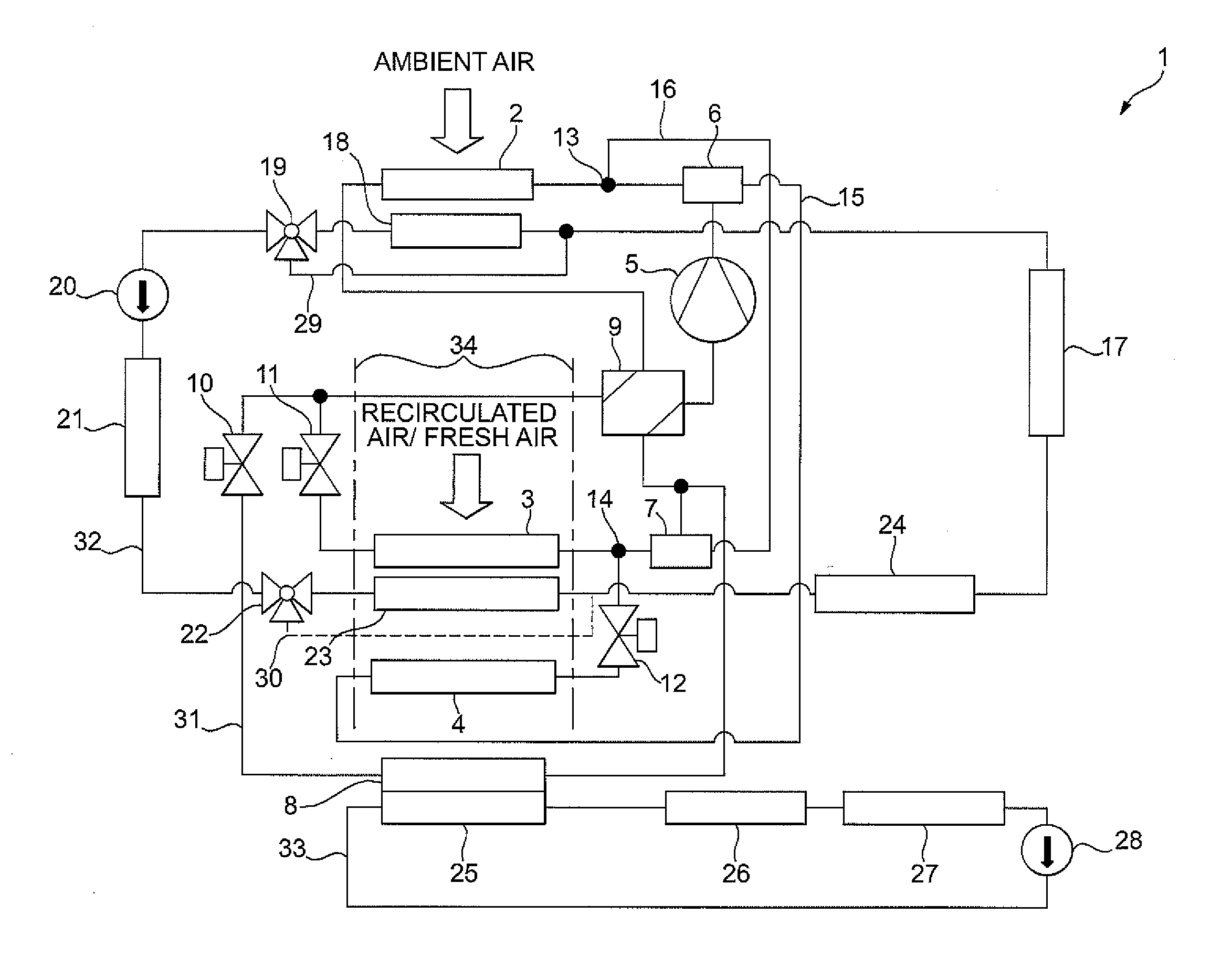
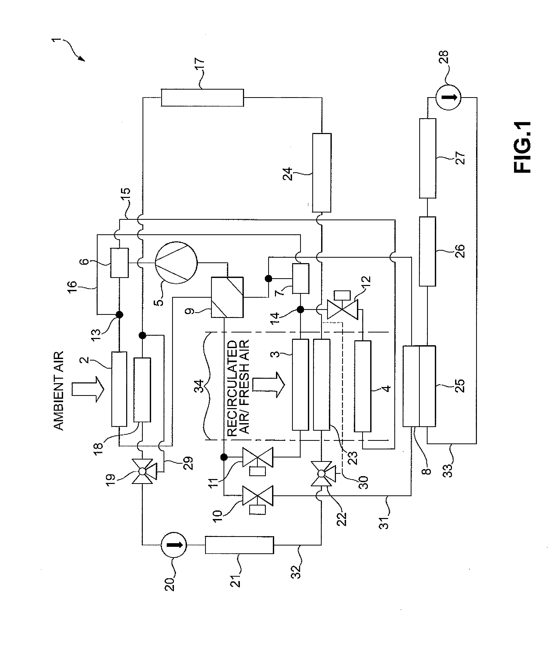
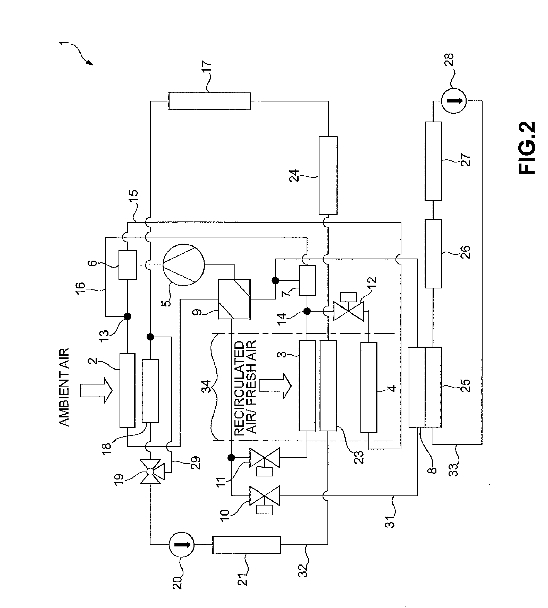
[0056]In FIG. 1 the HVAC system 1 with a refrigerant circuit 31 and two coolant circuits 32, 33 is shown.

[0057]Within the refrigerant circuit 31, in a direction of flow one after the other, an evaporator 3, a compressor 5, a condenser 2, and an expansion device 11 are provided. The components 2, 3, 5 are connected through a plurality of refrigerant conduits to form a closed primary circuit. Further, an inner heat exchanger 9 is optionally integrated into the primary circuit, the inner heat exchanger 9 serving to transfer heat between a liquid refriger...


PUM


Abstract

A method for operating an HVAC system includes the steps of adjusting a heating temperature of a heat exchanger disposed in a first flow passage, directing a first partial air mass flow through the first flow passage, directing a second partial air mass flow through a second flow passage, and directing the first partial air mass flow and the second partial air mass flow downstream of the first flow passage and the second flow passage, wherein the heating temperature of the heat exchanger required to at least one of achieve and maintain a desired climate in the passenger compartment of the vehicle is set as a maximum heating temperature for the heat exchanger, and wherein only an amount of energy required to at least one of achieve and maintain a desired climate in the passenger compartment of the vehicle is added to the HVAC system.

Description

CROSS-REFERENCE TO RELATED APPLICATION[0001]This application claims priority to German Patent Application Serial Number DE 10 2010 000 990.3 filed Jan. 19, 2010, the entire disclosure of which is hereby incorporated herein by reference.FIELD OF THE INVENTION[0002]The invention relates to a method for the operation of an HVAC (heating, ventilation, and air conditioning) system for vehicles.BACKGROUND OF THE INVENTION[0003]Typically, air to be supplied to a passenger compartment is conditioned using HVAC (heating, ventilation, and air conditioning) systems equipped with a refrigeration system for cooling the air and a coolant / air heat exchanger of an engine cooling circuit for heating the air. Additionally, conventional HVAC systems typically include air / air heat pumps and / or coolant / air heat pumps.[0004]In HVAC systems including a coolant / air heat exchanger, the system obtains heat from a cooling circuit of an internal combustion engine of the vehicle drive and conducts heat into the...

Claims


Application Information

Patent Timeline
Patent Type & Authority Applications(United States)
IPC IPC(8): F25D17/06
CPCB60H1/00064B60H1/00921B60H2001/00949B60H2001/00164B60H2001/00928B60H2001/00092
Inventor RICHTER, GERALDHAAS, TOBIASGRAAF, MARC
Owner HANON SYST
Why Eureka
Try Eureka