Pressure sensor device

Active Publication Date: 2011-07-21
ELTEK
View PDF4 Cites 16 Cited by
  • Summary
  • Abstract
  • Description
  • Claims
  • Application Information

AI Technical Summary

Benefits of technology

[0004]An object of the present invention is that of improving the reliability and operating accuracy of a sensor of the indicated type, in a simple and inexpensive manner. Such object is attained, accordin

Problems solved by technology

In some types of applications part of the fluid subjected to pressure measurement may accumulate in contact with, or inside, delicate components of the device, and specifically of the pressure sensor.
In case of low ambient temperature the accumulate

Method used


Image

  • Pressure sensor device
  • Pressure sensor device
  • Pressure sensor device

Examples


Embodiment Construction

[0018]The structure and general functionalities of the pressure sensor device according to the invention are similar to those of the devices illustrated and described in WO2008 / 078184; for such reason, hereinafter, the description of the components of the device according to the invention shall be relatively schematic, taking for granted that the practical details and preferred implementation characteristics of such components can be borrowed from the mentioned prior art document.

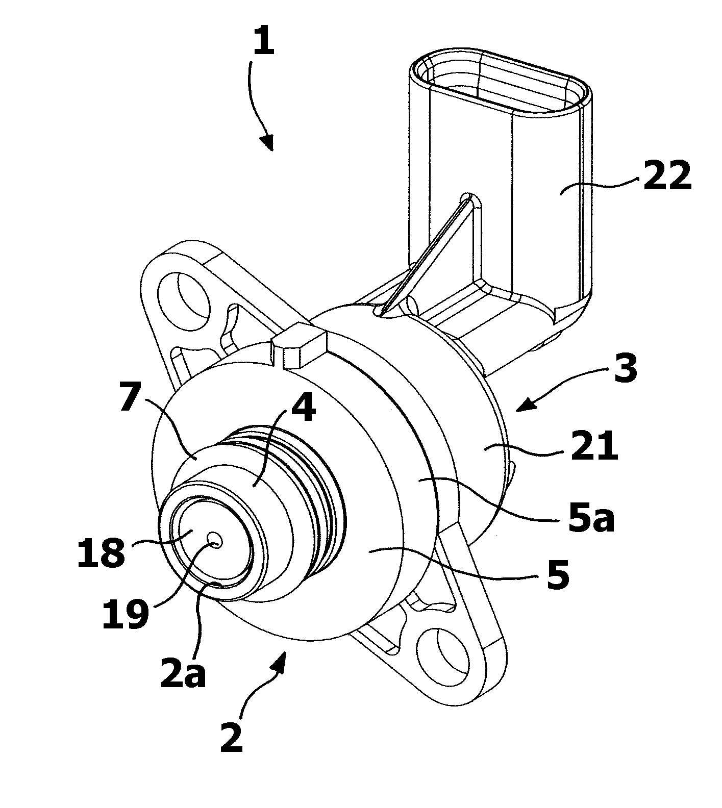
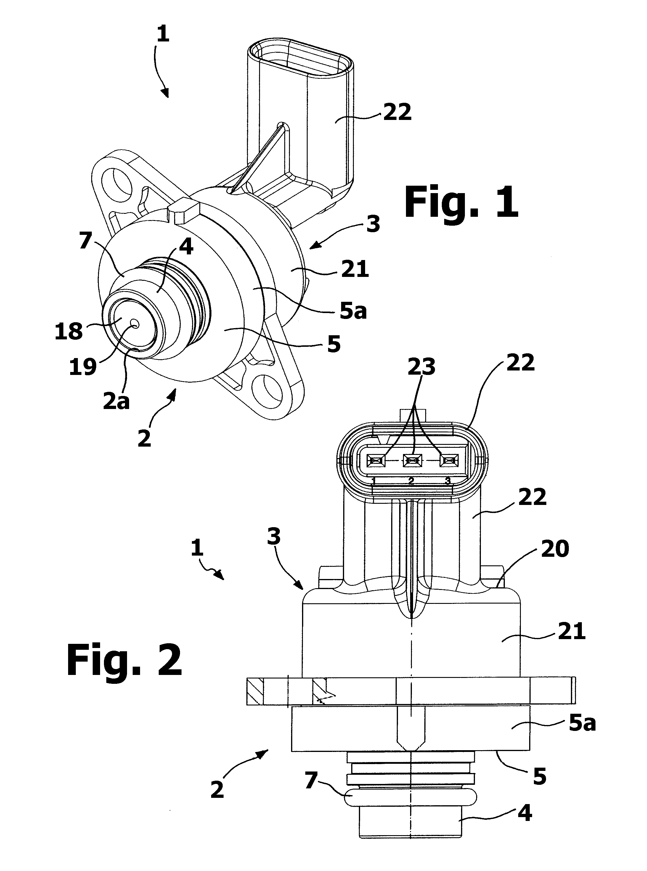
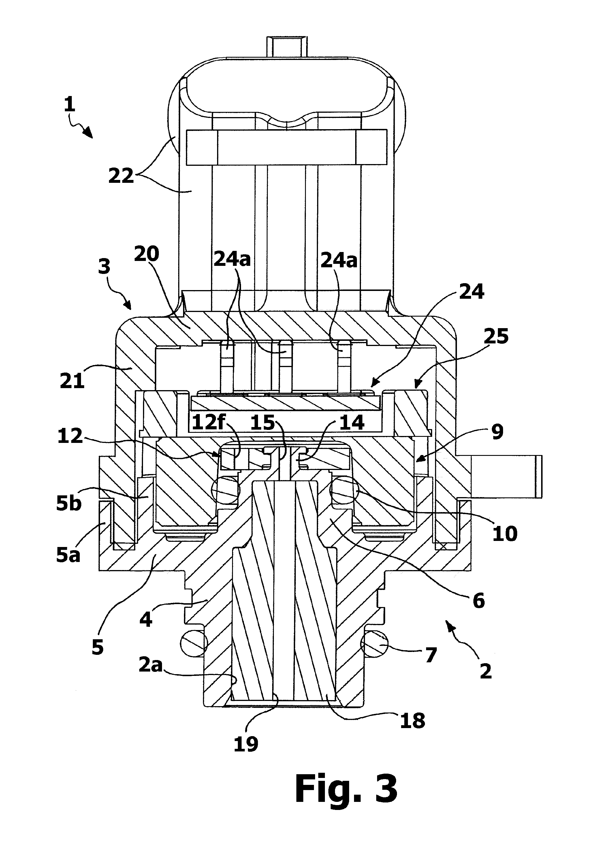
[0019]With reference to FIGS. 1-3, indicated in its entirety with 1 is a pressure sensor device according to the invention, whose structure comprises a part 2, which essentially performs support and hydraulic connection functions, and a part 3, which essentially performs cover and electrical connection or connector functions. The main body of the part 2, preferably made of relatively rigid material, such as for example thermoplastic material or metal material, is axially passed through by a cavity or passag...


PUM


Abstract

A pressure sensor device (1) comprises: a pressure sensor (9) having a sensor body (9a) defined in which is a cavity (11) with a bottom surface (11a) belonging to a membrane portion (9′) of the body itself, a detection element operatively being associated to the membrane portion (9′), a connection structure (2) having a duct (2a, 15, 19) in communication with the abovementioned cavity (11), designed to receive a fluid a pressure of which is to be detected. The connection structure comprises a body (2) for supporting the pressure sensor (9), defining at least one respective passage (2a), and one compressible element (12) designed to be in contact with the fluid and configured to compensate possible volume variations thereof, the compressible element (12) being positioned at least partially within the cavity (11), in such a manner to substantially divide it into two opposite regions. The device (1) is provided with connection passages (12f) for maintaining different regions of the cavity (11) in fluid communication, i.e. equilibrate in pressure.

Description

FIELD OF THE INVENTION[0001]The present invention refers to a pressure sensor device having the characteristics described in the preamble of claim 1. Such sensor device is known from document WO 2008 / 078184.PRIOR ART[0002]Devices of the indicated type comprise a casing into which a pressure sensor is mounted. The sensor has a body defining a cavity, whose bottom is formed by a membrane portion of the body itself, provided on which is a detection element. The fluid subjected to measurement is supplied to the abovementioned cavity, through a duct of the casing, in such a manner to cause a flexure of the membrane portion. The degree of such flexure, which depends on the pressure of the fluid, is measured by means of the detection element, whose output signal thus represents the pressure value. The sensor body is usually made of ceramic material and the detection element provided for on the membrane portion thereof is usually of the resistive or piezoresistive type.[0003]In some types o...

Claims


Application Information

Patent Timeline
IPC IPC(8): G01L9/00
CPCG01L9/0051G01L19/0038G01L19/06
Inventor ZORZETTO, MAUROMARTINENGO, GIORGIO
Owner ELTEK
Why Eureka
Try Eureka