

Central turbocharger mounting configuration for a twin-turbo engine
a technology for central turbochargers and twin-turbo engines, which is applied in the direction of combustion engines, machines/engines, internal combustion piston engines, etc., can solve the problems of inefficient use of space between the banks of the engine, increased hot piping, and complex ducting required for such twin-turbo configurations, so as to reduce the complexity of ducting configurations and free up more space around the engine. , the effect of reducing the complexity of ducting configuration
- Summary
- Abstract
- Description
- Claims
- Application Information
AI Technical Summary
Benefits of technology
Problems solved by technology
Method used
Image

Examples
Embodiment Construction
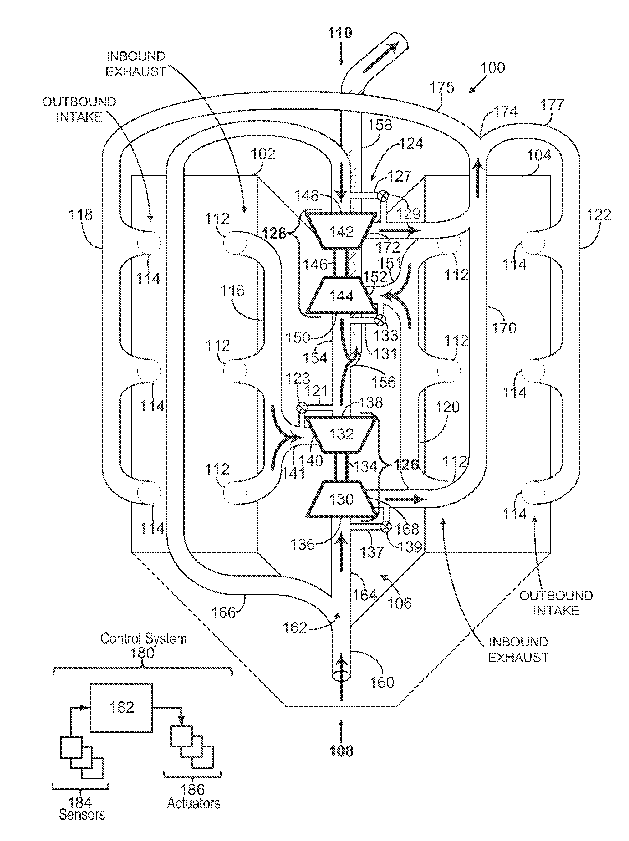
[0011]The following description relates to a multi-turbocharger V-engine configuration.
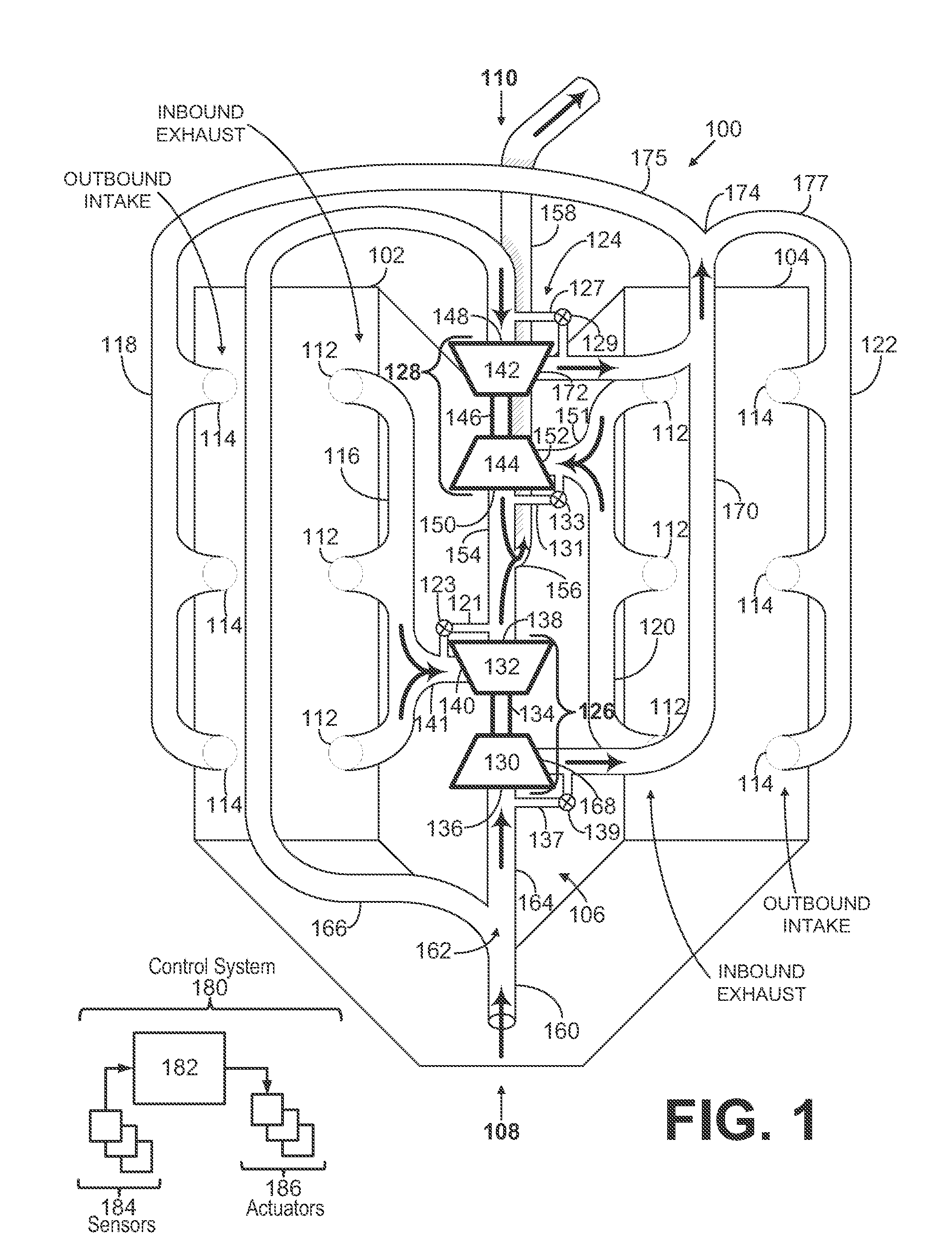
[0012]Various examples of the configuration are shown schematically in FIGS. 1-3. In some examples, an in-board exhaust configuration includes two turbochargers, one for each bank of the V-engine, arranged between the banks at least partly in the valley, as shown in FIG. 1. The turbine exits of each of the two turbochargers face one another and are combined together at a junction, before branching downward into the valley, and then traversing along the crankshaft axis out of the valley as shown in FIGS. 2A-2B and 3A-3B.
[0013]Specifically, the example V-engine shown schematically in FIGS. 1-3 includes two turbochargers positioned in a center portion of the engine between the banks of the engine above the valley formed by the banks so as to advantageously use space between the banks. Exhaust manifolds, coupled to in-board exhaust ports located on the banks, may include outlets oppositely positioned ...
PUM
 Abstract
Description
Claims
Application Information