
Panel fastening system

a technology for fastening systems and panels, which is applied in the direction of solar thermal energy generation, candle holders, lightening support devices, etc., can solve the problems of inconvenient installation, solar module manufacturers and suppliers don't produce this kind of mounting system, and heat in the environment, so as to achieve safe, fast and stable installation, and high tensile strength. , the effect of high tensile strength

Inactive Publication Date: 2011-07-21
RACWORTH
View PDF8 Cites 49 Cited by
  • Summary
  • Abstract
  • Description
  • Claims
  • Application Information

AI Technical Summary

Benefits of technology

[0018]An object of the present invention is to provide a fastening system for a panel which can be fastened on a surface of a mounted object via two mounting rails by engaging and to provide high tensile strength and simple installation. The present invention can fix different shapes of panel assemblies on a roof, the ground, a wall or a surface of a framework safely, quickly and stably; and the present invention has a simple structure, light weight and low total costs.
[0021]The cross section of each engaging slide block is shaped like C with a downward opening. Two grooves are formed in the cross section of the engaging slide block and respectively extend along the two ends of the engaging slide block to engage with the two protruding portions protruding from the inner sides of the two side lips of the opening of the engaging open cavity. A pair of opposite recesses with inclined faces is formed in the C-shaped opening to engage with the feet standing oppositely in the engaging open cavity. The engagement portions of the engaging slide blocks and the engagement portions of the mounting rail are fastened via fasteners to prevent the engaging slide blocks from sliding axially along the mounting rail in the engaging open cavities and avoid that the engaging slide blocks move horizontally and vertically in the engaging open cavities of the mounting rail and the engaging open cavities of the mounting rail produce deformation when the engaging slide blocks are acted upon by an external force. A threaded hole is formed in the center position between the two grooves of the engaging slide block and may be engaged with a matching fastening bolt.
[0041]Accordingly, comparing with the prior art, the present invention has the advantages as follows: basing on the engagement structure of the present invention, different sizes and shapes of solar modules or other panels can be fixed on a roof, the ground, a wall or a surface of a framework more safely, quickly and stably; and the present invention has the advantages of high tensile strength, light weight, simple installation and low costs.

Problems solved by technology

So solar photovoltaic power generation not only provides a lot of electric power, but also saves land occupation.
Recently, energy and environment problems become hot worldwide.
Most of solar module manufacturers and suppliers don't produce this kind of mounting system.
In the mounting method, the space between the tiles and the solar collectors is so small that the installation is inconvenient,
So the mounting method increases the difficulty and strength of installation, and can only be applied to the installation of the top of the solar modules.
Though the system can implement the installation of tops and back surfaces of solar modules and other panels, it needs that the rigidity of rails meets the demand of the tensile strength of the system, which will increase the wall thickness of the rails and cause an increase in the amount of mounting materials.
The whole mounting system needs three rails so that the amount of mounting materials is increased greatly, thereby the mounting costs and workloads are increased.
Hence, in conventional mounting systems for solar modules or other panels, few products can accomplish the fastening installation of tops or bottoms of solar modules or other panels on one mounting rail and the fastening connection of solar modules or other panels and the mounting rail on a surface of a mounted object.
Additionally, such conventional products, which can perform the above work using one rail, need to use heavy rails with large consumption in metals to improve tensile strength of their mounting systems, so the consumption of raw materials of the mounting systems is high.

Method used


Image

  • Panel fastening system
  • Panel fastening system
  • Panel fastening system

Examples


Embodiment Construction

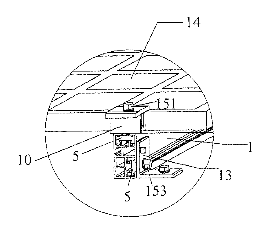
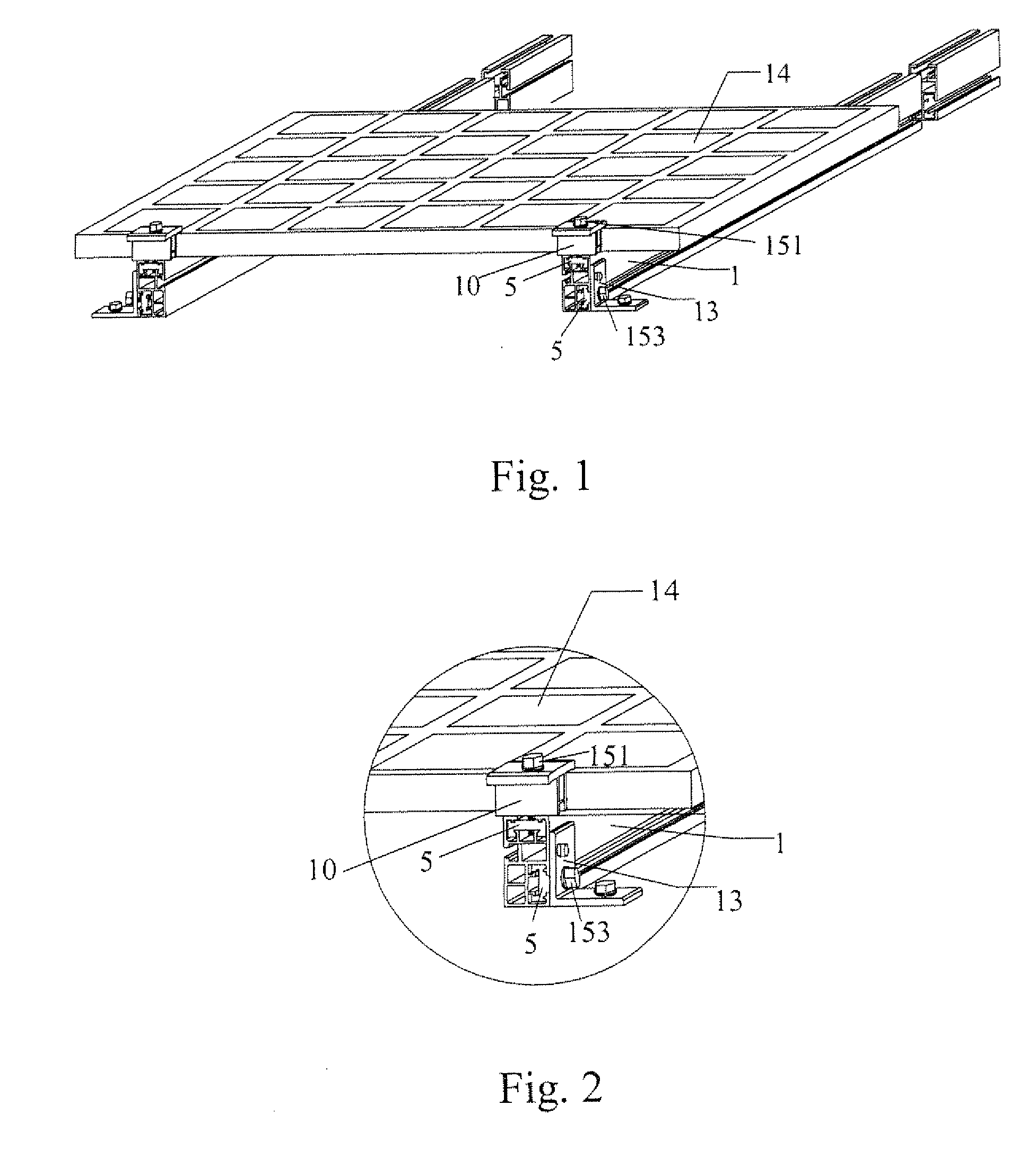
[0056]As shown in FIG. 1, number 5 indicates engaging slide blocks, number 10 indicates middle clamps, number 13 indicates L-shaped fasteners, and numbers 151 and 153 indicates fastening bolts. The preferred embodiment includes a panel 14 and two mounting rails 1, and the panel 14 is disposed on the mounting rails 1 to form a mounting system for solar modules or a plurality of other panels. The mounting rails 1 are formed by extruding aluminum alloy.

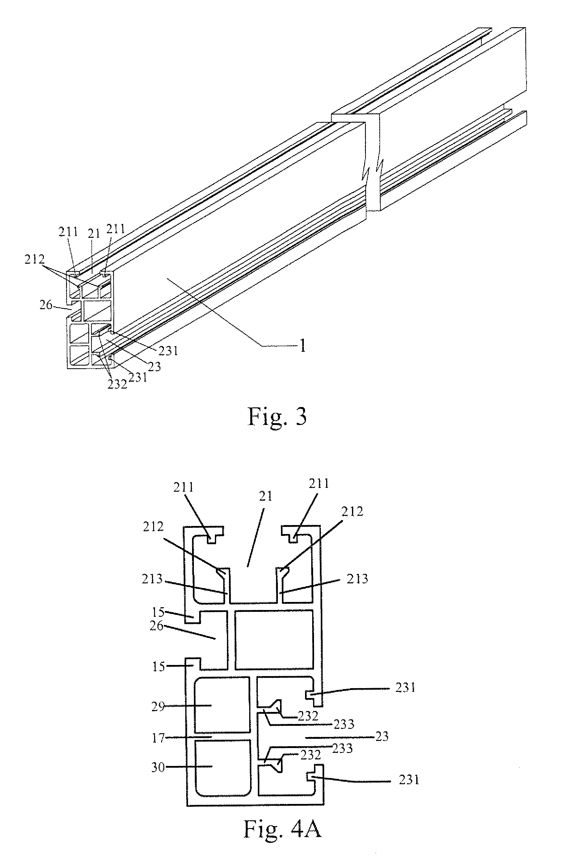
[0057]As shown in FIGS. 2-4, the mounting rails 1 each has a first engaging open cavity 21, a second engaging open cavity 23, a sliding open groove with a plane bottom 26, and two cavities 29, 30 which are spaced by a support 17.

[0058]The first engaging open cavity 21 is located in the upper portion of the section of the mounting rail 1 and extends axially along the mounting rail 1. The second engaging open cavity 23 is located below the right side of the first engaging open cavity 21 and forms an angle of 90 degrees with the first engag...


PUM


Abstract

The present invention discloses a fastening system for a panel. The fastening system includes: at least two mounting rails which each has a plurality of engaging open cavities formed therein; and a plurality of engaging slide blocks respectively engaging with the engaging open cavities; wherein the panel is disposed on the mounting rails and fixedly connected with the engaging slide blocks respectively. Basing on the engagement structure, the present invention can be fastened on a surface of a mounted object via two rails and provide high tensile strength and simple installation. The present invention can fix different shapes of panel assemblies on a roof, the ground, a wall or a surface of a framework safely, quickly and stably, and the present invention has a simple structure, light weight and low total costs.

Description

BACKGROUND OF THE INVENTION[0001]1. Field of the Invention[0002]The present invention relates to a mounting and fastening system for a panel, and more particularly to a mounting system for fastening solar modules or other panels. Specifically, one or a plurality of mounting rails and one or a plurality of solar modules or other panels are fastened via fasteners and corresponding engaging slide blocks and clamps to form a fastened assembly.[0003]2. Background of the Invention[0004]Solar energy, as one kind of sustained clean energy, has great potential in development and application. With the present situation of increasing globe energy demand, solar photovoltaic power generation is being developed rapidly as a sustainable substitution for energy.[0005]Solar photovoltaic power generation is a technology for converting solar energy into electrical energy, The core of the technology is semiconductor materials which can release electrons. The most common semiconductor material is silico...

Claims


Application Information

Patent Timeline
Patent Type & Authority Applications(United States)
IPC IPC(8): H01L23/12F16M13/00F16B2/02
CPCE05D15/0647F24J2/5205F24J2/5245F24J2/5254F24J2/5258H02S20/23Y02B10/12Y02B10/20Y02E10/47Y02E10/50H02S20/00F24J2002/5215F24S25/33F24S25/61F24S25/632F24S25/636F24S2025/801H02S20/10Y02B10/10
Inventor WU, WENQIANG
Owner RACWORTH
Learn More