Fluid regulator

Inactive Publication Date: 2011-07-21
ISOMATIC
View PDF13 Cites 19 Cited by
  • Summary
  • Abstract
  • Description
  • Claims
  • Application Information

AI Technical Summary

Benefits of technology

[0026]Another embodiment of said fluid pressure regulating unit can be achieved, if said pilot pressure applying means can be connected to a respective fluid pressure reservoir via a fluid throughput reducing means. Such a fluid throughput reducing means can be a throttle or an orifice ope

Problems solved by technology

The problem with the majority of presently existing pressure regulators is the usually high number of movable parts, necessary for the construction of the pressure regulator.
Apart from the costs involved with manufacturing and arranging a large number of movable parts, this also gives rise to vibration problems.
Such vibrations can lead to the generation of noise and a bad output pressure characteristics (i.e. randomly varying output pressure).
Another problem is that in the majority of presently available pressure reducers, the fluid, which pressure has to be reduced, has to change its moving direction several times, when flowing through the pressure regulator.
This can give rise to a slow pressure regulation response and therefore to a bad pressure output characteristics.
The output characteristics of such a pressure regulator

Method used


Image

  • Fluid regulator
  • Fluid regulator
  • Fluid regulator

Examples


Embodiment Construction

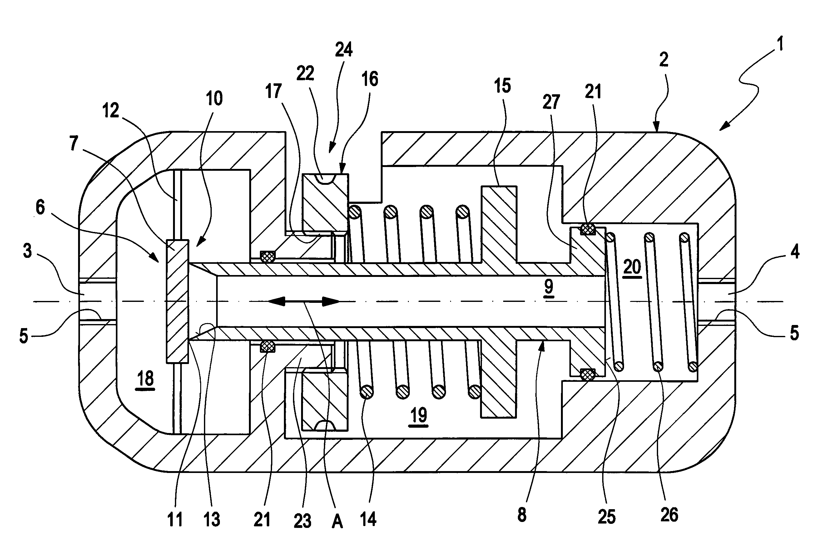
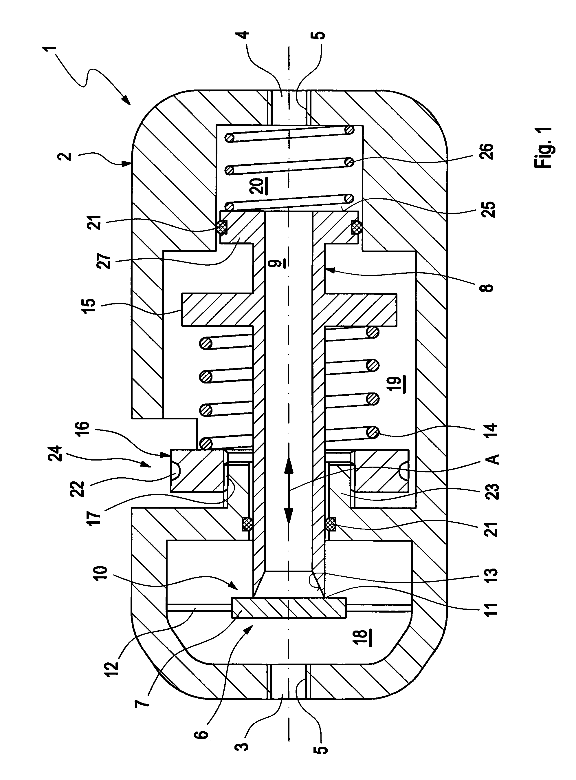
[0033]In FIG. 1, a schematical cross section through a first possible embodiment of a pressure regulator 1 is depicted. The pressure regulator 1 comprises a casing 2 with a fluid inlet port 3 and a fluid outlet port 4. Both fluid inlet port 3 and fluid outlet port 4 have an inner thread 5, so that a corresponding fluid pipe or fluid hose can be threadingly engaged in the respective fluid port 3, 4.

[0034]Within the casing 2 of the pressure regulator 1, a valve unit 6 is arranged. The valve unit 6 essentially consists of a valve seat 7 and a valve tube 8. The valve tube 8 can be moved in an axial direction (as indicated by double-headed arrow A) within the casing 2 of the pressure regulator 1.

[0035]The valve tube 8 is designed to have a hollow interior 9, forming an inner fluid line 9 through the valve tube 8. The contacting area between valve seat 7 and valve tube 8 forms the valve opening 10. If the valve tube 8 is in its leftmost position (as drawn in FIG. 1), the valve seat 7 and ...


PUM


Abstract

A fluid pressure regulating unit (1, 28, 35, 56, 58), comprises a fluid inlet port (3), a fluid outlet port (4), a valve means (6) and a main valve biasing means (14, 36). The main valve biasing means (14) biases said valve means (6) in the direction of an open position. An auxiliary valve biasing means (26) is provided, biasing the valve means (6) in the direction of a closed position.

Description

CROSS REFERENCE TO RELATED APPLICATIONS[0001]This application is entitled to the benefit of and incorporates by reference essential subject matter disclosed in International Patent Application No. PCT / DK2009 / 000208 filed on Sep. 17, 2009 and European Patent Application No. 08016555.8 filed on Sep. 19, 2008.FIELD OF THE INVENTION[0002]The invention relates to a fluid pressure regulating unit, comprising a fluid inlet port, a fluid outlet port, a valve means and a main valve biasing means, wherein said main valve biasing means biases said valve means in the direction of a first position.BACKGROUND OF THE INVENTION[0003]Fluid regulators as such are well known in the state of the art. They are used to reduce the pressure of a fluid, entering the fluid regulator on a high pressure side, to a lower pressure level on the fluid outlet side. Preferably, the pressure on the fluid outlet side will be essentially constant. Such pressure regulating units are used, for example, for pressurized ga...

Claims


Application Information

Patent Timeline
IPC IPC(8): F16K1/00
CPCG05D16/103F16K1/307F16K15/063F16K31/1226F16K17/06F16K31/1221F16K31/1223F16K17/044Y10T137/7836Y10T137/7762Y10T137/7835Y10T137/7905
Inventor KRISTOFFERSEN, SOEREN
Owner ISOMATIC
Why Eureka
Try Eureka