
Wind energy plant testing device

a testing device and wind energy technology, applied in the direction of testing circuits, machines/engines, instruments, etc., can solve the problems that the appropriate measurement is not practical on the real public grid system, and achieve the effect of short switching time, short switching time, and different sudden voltage change levels

Active Publication Date: 2011-07-21
SENVION GMBH
View PDF6 Cites 12 Cited by
  • Summary
  • Abstract
  • Description
  • Claims
  • Application Information

AI Technical Summary

Benefits of technology

[0006]The present invention is based on the object of improving a test device of the type mentioned initially such that it can be adjusted more freely in order to also test for grid system faults other than shorts.

Problems solved by technology

These are based on the knowledge that appropriate measurements are not actually practical on the real public grid system.

Method used


Image

  • Wind energy plant testing device
  • Wind energy plant testing device
  • Wind energy plant testing device

Examples


Embodiment Construction

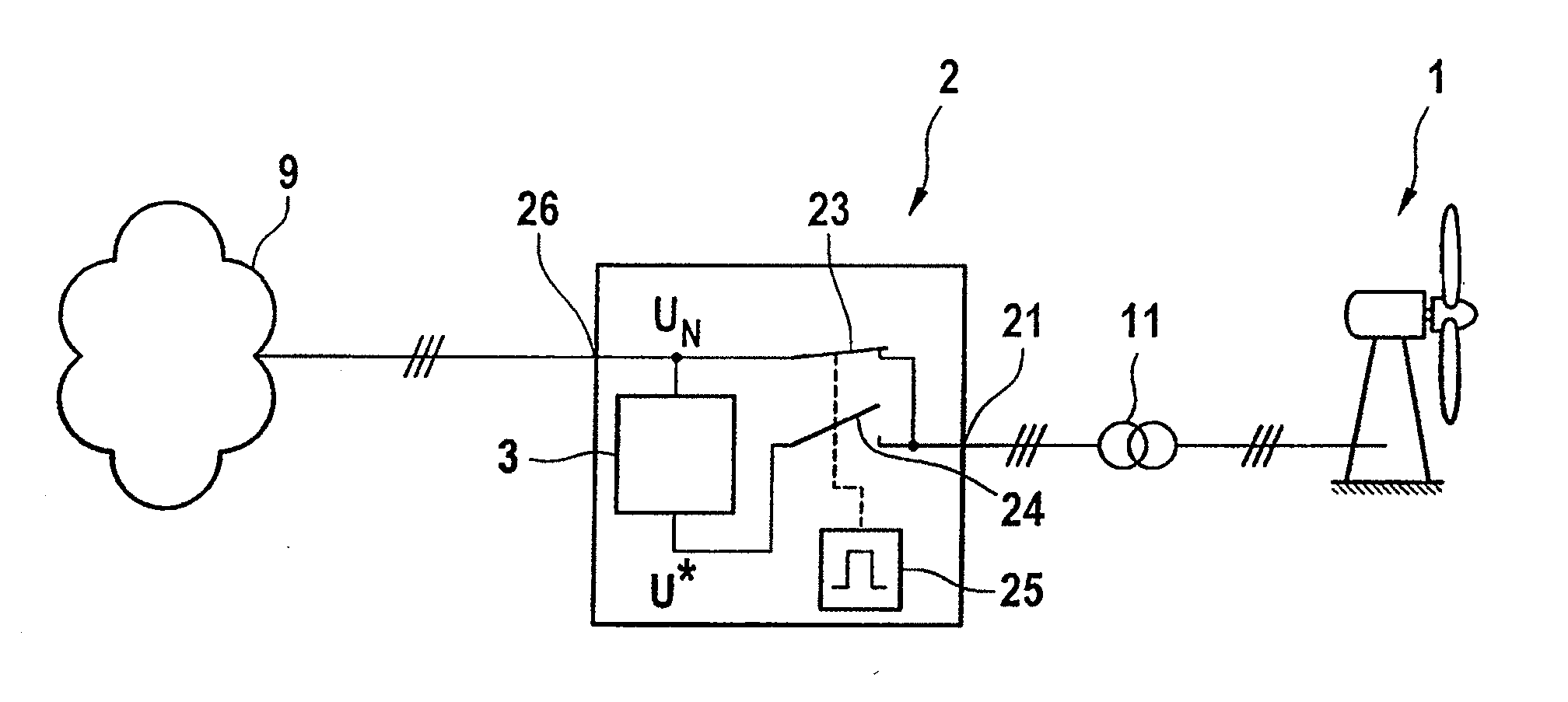
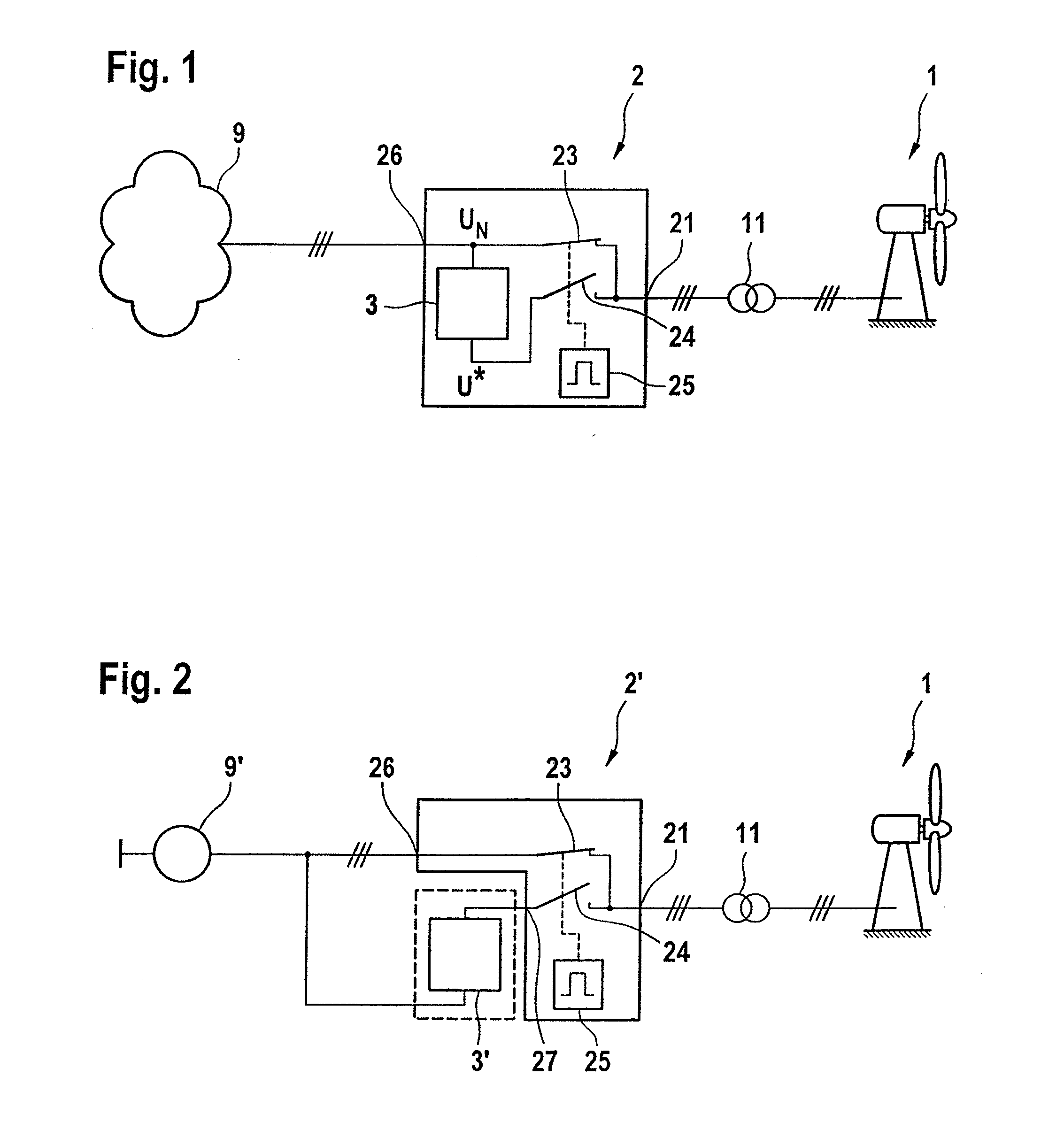
[0034]Test devices according to the present invention are used to test the behavior of a wind energy installation 1 on the electrical grid system. An actually existing public electricity grid system 9 can be used as the electricity grid system, or it is possible to use one or more voltage sources 9′, which simulate the electrical grid system.

[0035]The test device, which is annotated in its totality with the reference number 2 or 2′, is respectively connected between the wind energy installation 1 and the electrical grid system 9, or the voltage source 9′ which acts as a substitute for it. In this case, the transformer 11, which is generally in the form of a medium-voltage trans-former of the wind energy installation 1, is normally connected between the test device 2 and the wind energy installation 1. This applies in any case to a wind energy installation 1 with a doubly-fed asynchronous generator. In other embodiments, the test device may if required be connected between the wind e...


PUM


Abstract

A wind energy installation test device for defined production of grid system faults, and a method thereof. The test device can include an output configured to connect to a wind energy installation, an input configured to connect to a grid system, and a switching device for connection of an electrical disturbance component relating to a grid system parameter. An autotransformer can be used for the electrical disturbance component. The grid system in a sound state can be connected to a primary winding connection and the grid system in a disturbed state with respect to the grid system parameter can be output at a secondary winding connection.

Description

REFERENCE TO RELATED APPLICATIONS[0001]This application is a national stage application under 35 USC 371 of International Application No. PCT / EP2009 / 007028, filed Sep. 30, 2009, which claims the priority of German Patent Application No. 10 2008 049 629.4, filed Sep. 30, 2008, the contents of which prior applications are incorporated herein by reference.FIELD OF THE INVENTION[0002]The invention relates to a test device for wind energy installations. The test device has an output and an input, wherein the wind energy installation is connected to the output and wherein a grid system can be connected to the input, and a switching device is provided for connection of an electrical disturbance component relating to a grid system parameter.BACKGROUND OF THE INVENTION[0003]With the increasingly widespread use of wind energy installations, these installations have to satisfy more stringent requirements relating to their behavior with respect to the grid system. This is particularly true for ...

Claims


Application Information

Patent Timeline
Patent Type & Authority Applications(United States)
IPC IPC(8): G01R31/00G01R31/50
CPCG01R31/02Y02E10/763H02J3/386F03D17/00G01R31/50H02J2300/28H02J3/381G01R31/343Y02E10/76
Inventor LETAS, HEINZ-HERMANN
Owner SENVION GMBH
Features
  • Generate Ideas
  • Intellectual Property
  • Life Sciences
  • Materials
  • Tech Scout
  • Unparalleled Data Quality
  • Higher Quality Content
  • 60% Fewer Hallucinations
Learn More