Image processing apparatus and image processing method therefor
a technology of image processing apparatus and image processing method, which is applied in the field of image processing apparatus, can solve the problems of loss of laser intensity near the end of the photosensitive drum, inability to perform density tone correction process with high accuracy, and inability to print output images that change color tones, etc., and achieve high-accuracy density tone correction, profile creation, and the effect of reducing the burden on the user
- Summary
- Abstract
- Description
- Claims
- Application Information
AI Technical Summary
Benefits of technology
Problems solved by technology
Method used
Image
Examples
first embodiment
[0047]Next, a process flow of an image processing apparatus according to a first embodiment will be described in detail with reference to a flowchart in FIG. 3 and an exemplary evaluation image in FIG. 4.
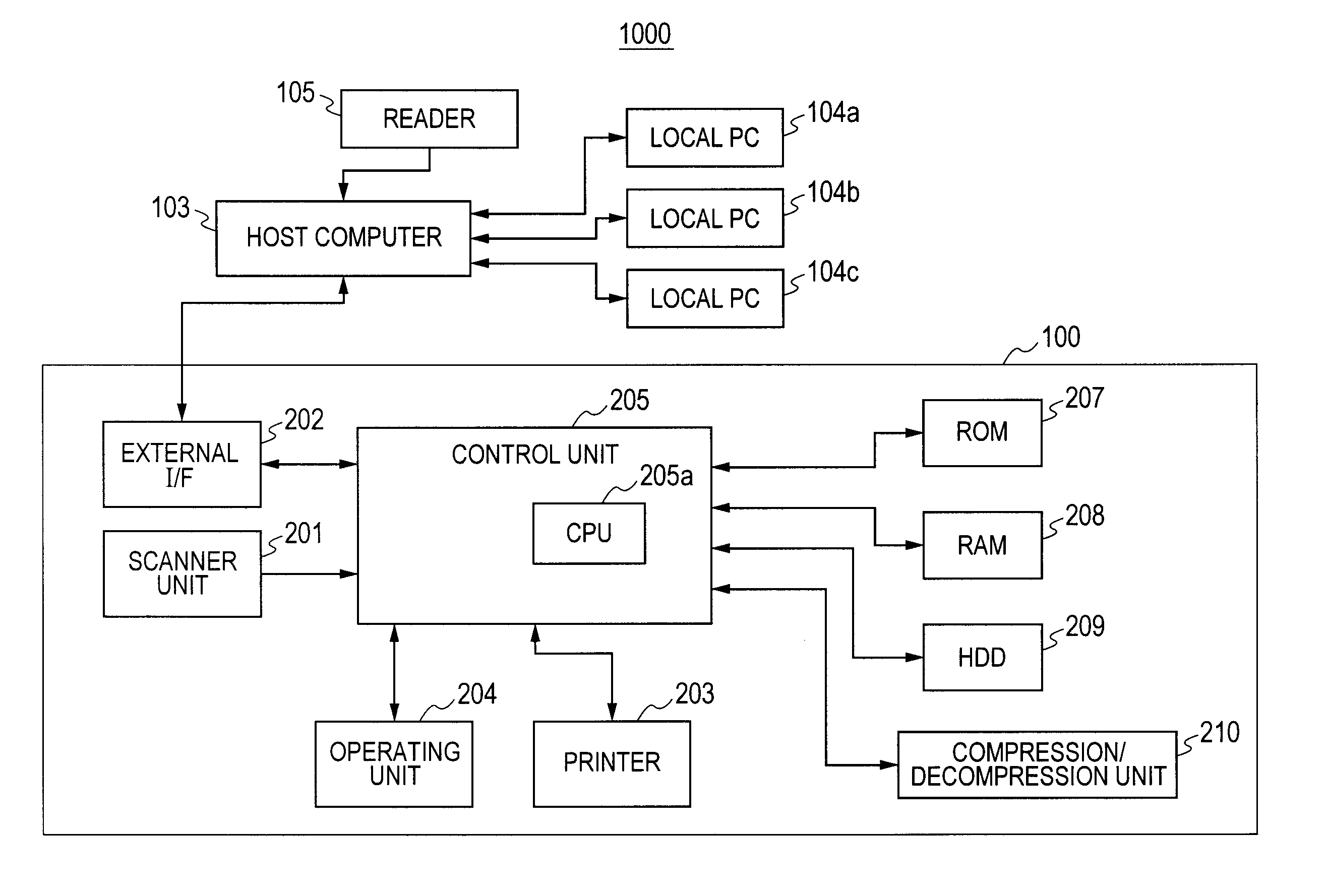
[0048]First, the user starts density tone correction software preinstalled on the host computer 103. Then, the user issues a command to perform density tone correction using a density tone correction command screen 10000 (FIG. 10) displayed on the computer 103 (S3001). To give a command to perform density tone correction, the user can press a “Yes” button 10001 first, and then press a “Density Irregularity Correction” button 10002. Although the user is allowed to select between Normal mode and Density Irregularity Correction mode in FIG. 10, this is not restrictive, and only the Density Irregularity Correction mode may be displayed. In response to the command, the printer 203 of the printing device 100 prints an evaluation image 4000 (S3002).
[0049]As shown in FIG. 4, multiple color ...
second embodiment
[0061]Next, a process flow of an image processing apparatus according to a second embodiment will be described in detail with reference to a flowchart in FIG. 5 and an exemplary evaluation image in FIG. 6. In the second embodiment, density irregularity correction can be performed by taking into consideration density irregularities in a sub-scanning direction in addition to density irregularities in the main scanning direction.
[0062]As shown in FIG. 6, multiple color patches and multiple reference patches except some peripheral patches are placed alternately on the same main scanning line of an evaluation image 6000, where all the patches have the same process color (one of cyan C, magenta M, yellow Y, and black K). Also, when compared between adjacent process colors in the sub-scanning direction, multiple color patches and multiple reference patches are placed in such a way as to alternate each other in the sub-scanning direction. The multiple color patches are identical in process ...
third embodiment
[0073]Next, a process flow of an image processing apparatus according to a third embodiment will be described in detail with reference to a flowchart in FIG. 7 and an exemplary evaluation image in FIG. 8. In the third embodiment, density irregularity correction is performed during profile creation.
[0074]To create a color profile, the user starts profile creation software preinstalled on the host computer 103. Then, by following instructions on a UI of the profile creation software, the user issues a command to create an evaluation image (hereinafter referred to as a color chart) 8000 for profile creation (S7001). In response, the printer 203 prints the color chart (S7002).
[0075]Multiple color patches and multiple reference patches are placed alternately on the color chart. The multiple color patches are patches of various colors created by mixing multiple process colors (cyan, magenta, yellow, and black). Also, the multiple reference patches are created using the same density signal...
PUM
 Abstract
Description
Claims
Application Information
 - R&D
- Intellectual Property
- Life Sciences
- Materials
- Tech Scout
- Unparalleled Data Quality
- Higher Quality Content
- 60% Fewer Hallucinations
Browse by: Latest US Patents, China's latest patents, Technical Efficacy Thesaurus, Application Domain, Technology Topic, Popular Technical Reports.
© 2025 PatSnap. All rights reserved.Legal|Privacy policy|Modern Slavery Act Transparency Statement|Sitemap|About US| Contact US: help@patsnap.com


