
Image encoding/decoding method and apparatus using block transformation

a video and block transformation technology, applied in the field of video encoding/decoding methods and apparatus using block transformation, can solve the problems of low efficiency of compression, degrade the subjective video quality at low band transmission bit rate, degrade the accuracy of intra prediction and in turn the compression efficiency, and achieve the effect of improving the accuracy of block prediction, improving compression efficiency, and efficient encoding/decoding of video

Active Publication Date: 2011-07-21
SK TELECOM CO LTD
View PDF13 Cites 42 Cited by
  • Summary
  • Abstract
  • Description
  • Claims
  • Application Information

AI Technical Summary

Benefits of technology

[0021]As described above, according to the disclosure, the current block of a video is predicted from the adjacent blocks for encoding / decoding the video wherein the prediction of the pixels in the block can be performed starting from the adjacent pixels with the highest proximity in the spatial prediction direction, thereby improving the accuracy of the block predictions toward a better compression efficiency to achieve an efficient encoding / decoding of the video.

Problems solved by technology

Conventional video coding methods use “intra prediction” for coefficients transformed in Discrete Cosine Transform Domain (or DCT Transform Domain) to seek higher encoding efficiency resulting in degradation of the subjective video quality at low band transmission bit rates.
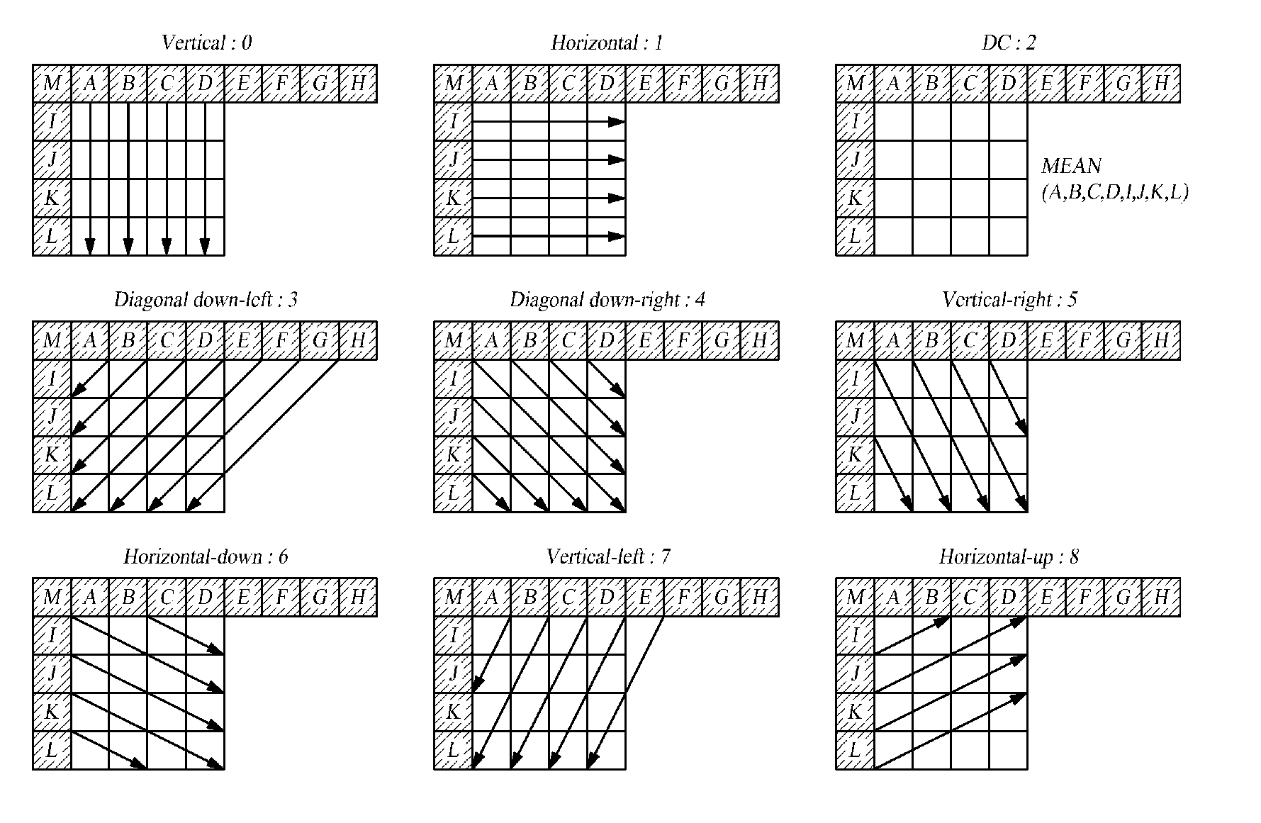
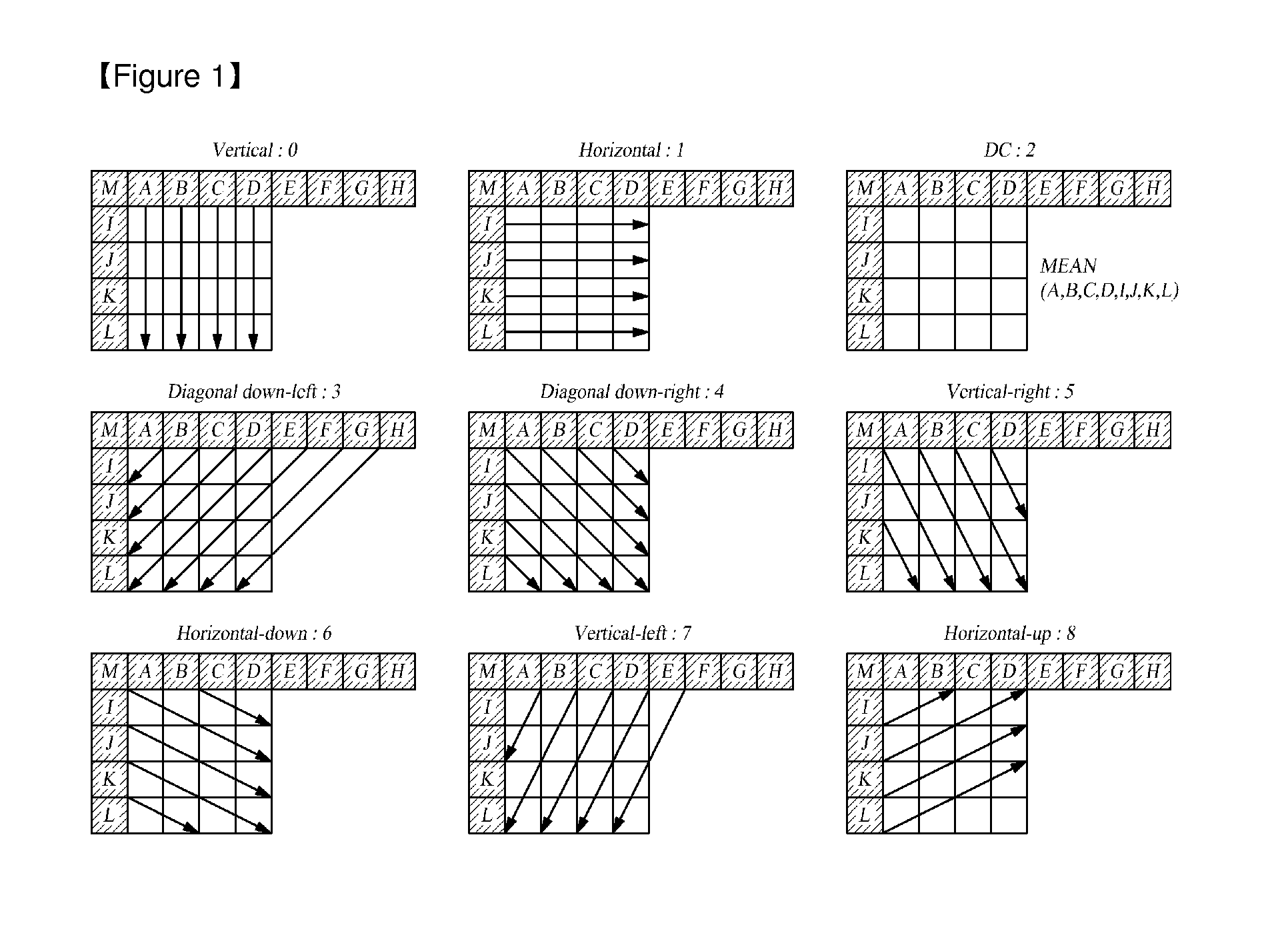
However, performing the intra predictions by such regular square blocks may degrade the accuracy of prediction since the pixels to be predicted are predicted using relatively distant pixels, resulting in low efficiency of the compression.
In this case, the pixels a0˜p0 are predicted from the adjacent pixels A˜P with the spatially closest proximity in the direction of prediction, but the pixels a1˜p1 are spatially distanced from the adjacent pixels A˜P by two pixels as the pixels a15˜p15 are spatially distanced from the adjacent pixels A˜P by sixteen pixels, which degrades the accuracy of the intra prediction and in turn the compression efficiency.

Method used


Image

  • Image encoding/decoding method and apparatus using block transformation
  • Image encoding/decoding method and apparatus using block transformation
  • Image encoding/decoding method and apparatus using block transformation

Examples


Embodiment Construction

[0035]FIG. 4 is a schematic block diagram of an electronic configuration of a video encoding apparatus according to an embodiment.

[0036]A video encoding apparatus 400 according to an embodiment of the present disclosure is configured to encode a video having a current block with pixels by using one or more respectively adjacent pixels encoded prior to encoding the current block pixels and each having the highest proximity to the respective current pixels in a predetermined prediction direction, and the encoding apparatus 400 may be comprised of a block rectangle-shaper 410, an intra predictor 420, a subtractor 430, a rearranger 440, a transformer 450, a quantizer 460, and an encoder 470. Here, the current block may be a block sized L×M with L being unequal to M.

[0037]Video encoder 400 may be a personal computer or PC, notebook or laptop computer, personal digital assistant or PDA, portable multimedia player or PMP, PlayStation Portable or PSP, or mobile communication terminal or suc...


PUM


Abstract

Video encoding / decoding method and apparatus using a block transformation are disclosed. The apparatus encodes the video through predicting each pixel in a current block of the video by using one or more adjacent pixels, which are encoded prior to encoding the current block and have the closest proximity to the pixels respectively in a predetermined prediction direction, and wherein the current block is sized L×M with L being unequal to M. It has become possible to predict the pixels in the block starting from closest one of the pixels in the prediction direction in order to provide more accurate block predictions and then raise the compression efficiency that leaps to more efficient video encoding / decoding performance.

Description

TECHNICAL FIELD[0001]The present disclosure relates to a video encoding / decoding method and apparatus using a block transformation. More particularly, the present invention relates to a video encoding / decoding method for a current block through its prediction from the adjacent blocks wherein predictions are performed on the entire pixels of the current block starting from closest one of the pixels in the prediction direction.Background Art[0002]Moving Picture Experts Group (MPEG) and Video Coding Experts Group (VCEG) have developed an improved and excellent video compression technology over existing MPEG-4 Part 2 and H.263 standards. The new standard is called H.264 / AVC (Advanced Video Coding) and was released simultaneously as MPEG-4 Part 10 AVC and ITU-T Recommendation H.264. Such H.264 / AVC (hereinafter referred to as ‘H.264’) uses a spatial predictive coding method, which is different from conventional video coding international standards such as MPEG-1, MPEG-2, MPEG-4 Part2 Visu...

Claims


Application Information

Patent Timeline
Patent Type & Authority Applications(United States)
IPC IPC(8): H04N7/12
CPCH04N19/593H04N19/176H04N19/51
Inventor KIM, HAYOONLEE, YUNGLYULMOON, JOOHEEKIM, HAEKWANGJEON, BYEUNGWOOHAN, KIHUN
Owner SK TELECOM CO LTD
Learn More