[0009]It is therefore an object of the invention to provide a turbine blade or vane of the type mentioned in the introduction for a gas turbine, which can be cooled efficiently and sufficiently using the smallest quantity of coolant possible and / or in which a casting core in a casting apparatus which can be handled particularly robustly can be used for production.
[0011]The invention is based on the recognition that it is possible to achieve a more stable casting core if the first openings arranged in the casting core
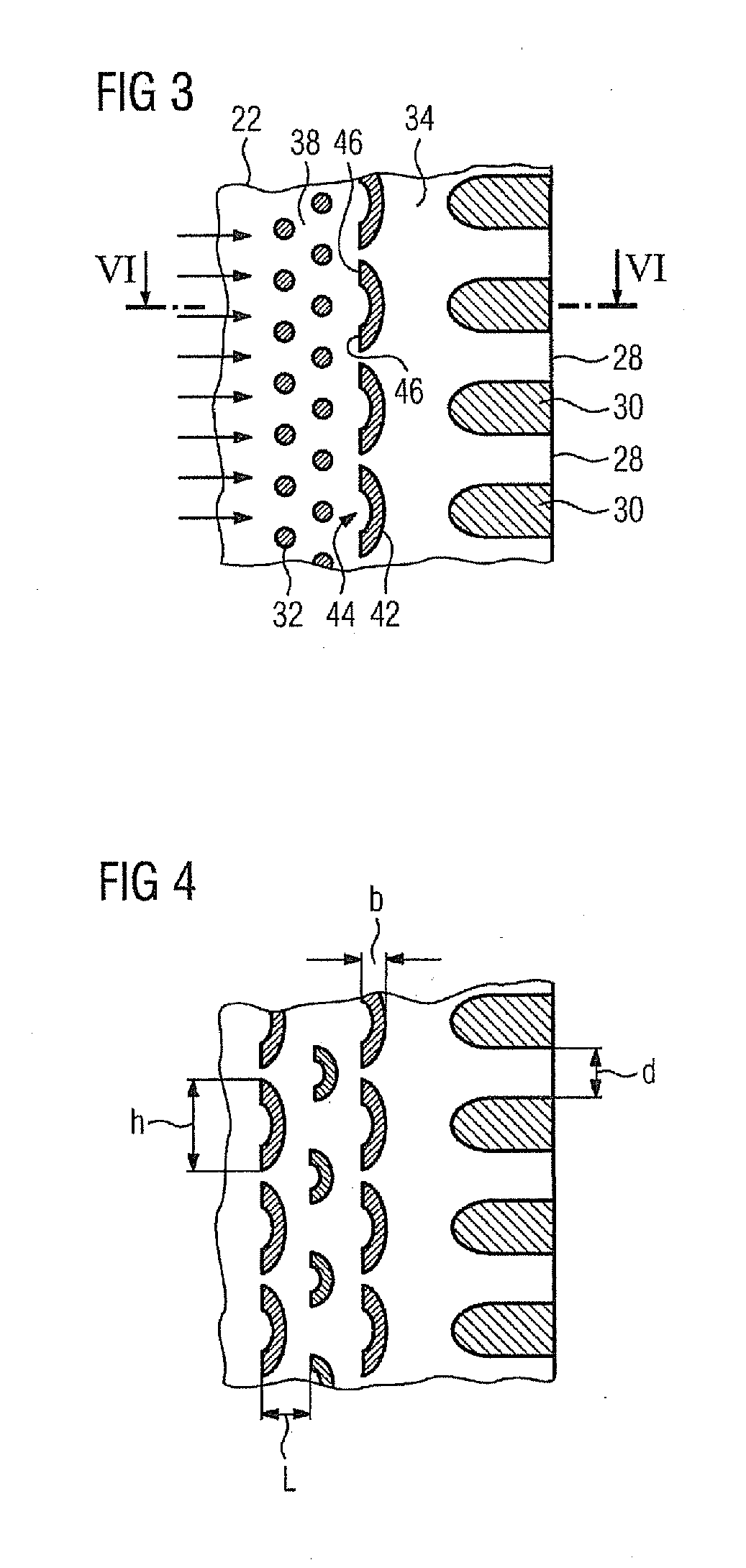
trailing edge are further reduced in size in longitudinal section, such that the separating webs arranged therebetween in the casting core are widened. However, in a turbine blade or vane produced with such a casting core, this widening of the separating webs arranged in the casting core enlarges the openings arranged at the trailing edge, through which the coolant escapes from the turbine blade or vane. Since these openings have also served to date for setting the coolant consumption, enlarged openings thus lead to an increased consumption of coolant. In principle, this increase is undesirable and reduces the efficiency of the gas turbine. In order to counter this effect, therefore, the invention proposes to increase the pressure loss in the region upstream from the trailing edge openings in the turbine blade or vane (more precisely: in a cavity arranged fluidically upstream from the openings) and therefore to provide an increased flow resistance there, in order to compensate, if not even overcompensate, for the above-mentioned effect of increased passage of coolant. In order to achieve a further increased pressure loss—compared with the cylindrical pin fins known from the prior art—in the flow of coolant upstream from the openings at the trailing edge of the turbine blade or vane, the invention proposes to provide a plurality of turbulence elements upstream from the webs, which turbulence elements each have an incident-flow side which faces toward the flow of coolant arriving there and is at least partially concavely curved. This measure makes it possible to accept an enlargement of the openings without an increased consumption of coolant being established as a result.
[0012]A further
advantage of the concavely curved incident-flow side of the turbulence elements is a further increase in the transfer of heat between the inner surfaces of the side walls of the main blade or vane part and the flow of coolant which flows along the latter as a result of further increased turbulence in the coolant.
[0021]According to a first advantageous development, the turbulence elements can be arranged directly upstream from the webs in at least one row transversely to the main direction of flow of the coolant. In this case, it is preferable for each of the turbulence elements in the row to have an at least partially concavely curved incident-flow side. It is thereby possible to set a uniform pressure loss for the coolant and a uniform transfer of heat over the entire longitudinal extent of the turbine blade or vane—in other words: over the entire height of the main blade or vane part. However, it is also conceivable to provide different geometries of turbulence elements according to the invention or else different distances in a row, in order to meet local demands relating to the cooling.
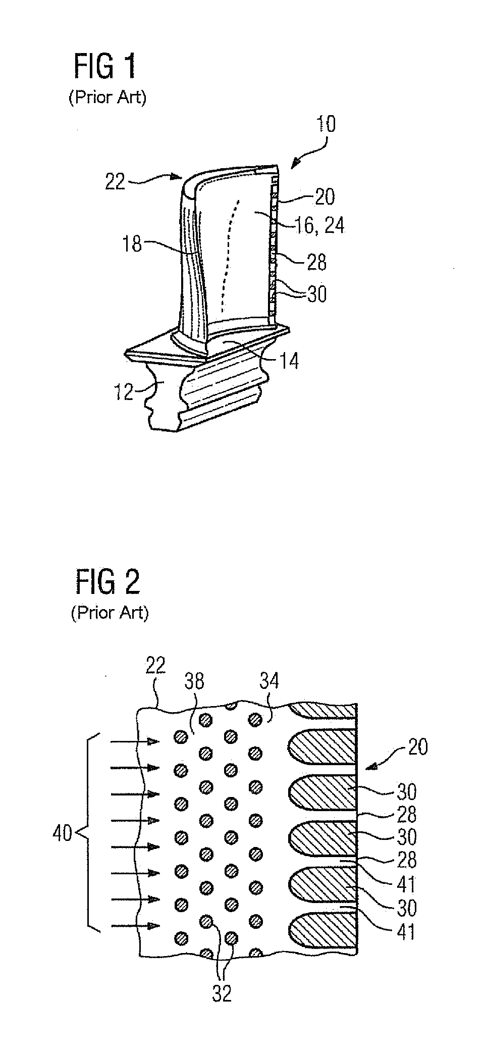
[0023]According to a further advantageous refinement, it is possible for a further means for stimulating the turbulence of the coolant flowing through the cavity to the openings to be provided upstream and / or downstream from the turbulence elements. In this case, the further means may comprise a multiplicity of pillars or pedestals arranged in a grid, i.e. the cylindrical pin fins known from the prior art. As an alternative or in addition, it is also conceivable for the further means to be formed from at least one further row of turbulence elements according to the invention. Consequently, it is possible not only for a
single row of turbulence elements according to the invention to be present, but also a plurality of rows of turbulence elements according to the invention, which are each preferably oriented perpendicularly to the flow of coolant. This further increases the pressure loss.
[0025]According to the invention, it is provided that at least one of the second openings is at least partially concavely shaped. In order to form correspondingly shaped turbulence elements in the turbine blade or vane, the concave part of the second openings faces away from the casting core trailing edge. Such a casting core can be used to produce turbine blades or vanes according to the invention which, upstream from the webs, i.e. in the interior of the turbine blade or vane, produce a relatively
high pressure loss for the coolant, as a result of which the webs present between the openings provided in the turbine blade or vane trailing edge can be made narrower. Here, the narrower webs are obtained using a casting core of which the first openings at the casting core trailing edge are likewise narrower. Separating webs present between the first openings in the casting core—which separating webs define the openings in the trailing edge in the cast turbine blade or vane—have—with respect to the
conventional casting core—a relatively wide form, and this increases the overall stability of the casting core. In the vicinity of the casting core trailing edge, a casting core configured according to the invention is therefore less likely to fracture than a
conventional casting core and can accordingly be handled with greater ease and more robustly.

