
Arrangement with heat exchanger for thermoelectric generators of motor vehicles

A technology of thermoelectric generators and heat exchangers, which is applied in the direction of heat exchange equipment, thermoelectric devices and heat exchangers that only use the Peltier or Seebeck effect

Active Publication Date: 2017-02-22
VTESCO TECH GMBH
View PDF7 Cites 0 Cited by
  • Summary
  • Abstract
  • Description
  • Claims
  • Application Information

AI Technical Summary

Problems solved by technology

The arrangement of thermoelectric generators comprising thermoelectric elements leads to the problem that, on the one hand, since as much heat as possible from the exhaust gas is required for the production of electrical energy, and therefore a corresponding arrangement of closed connections would be advantageous, on the other hand , the restricted space conditions and the maximum allowable temperature must be considered

Method used


Image

  • Arrangement with heat exchanger for thermoelectric generators of motor vehicles
  • Arrangement with heat exchanger for thermoelectric generators of motor vehicles
  • Arrangement with heat exchanger for thermoelectric generators of motor vehicles

Examples


Embodiment Construction

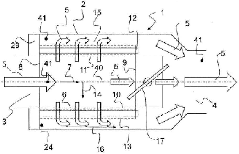
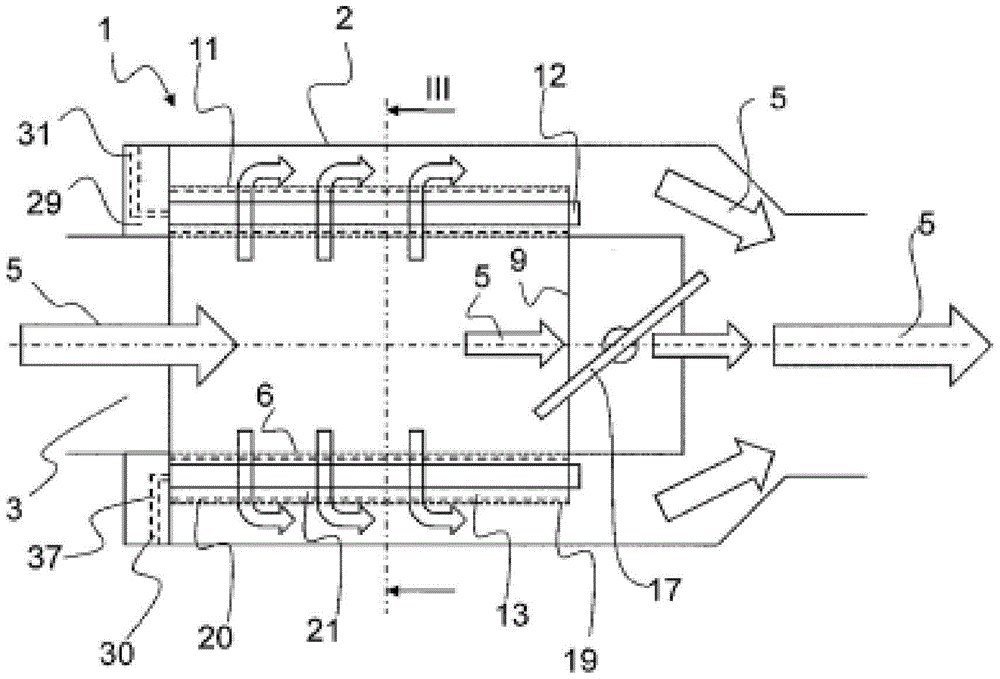
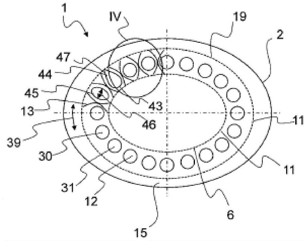
[0044] figure 1 A longitudinal section of the heat exchanger 1 is shown. The fluid 5 (or exhaust gas) flows through the inlet 3 in the axial direction 7 and into the inner pipe 6 of the heat exchanger 1 through the first end side 8 , which is fluidically connected to the inlet 3 . Here, the fluid flow is deflected at least partially, so that the fluid 5 then flows in the radial direction 14 in the direction of the first peripheral surface 10 of the inner pipe 6 . The fluid 5 passes through the first peripheral surface 10 through the opening 11 and impinges on the heat exchanger tubes 12 arranged at the outside of the first peripheral surface 10 . Arranged between the heat exchanger tubes 12 is a guide element 13 which guides the fluid 5 around the heat exchanger tubes 12 . The fluid 5 flowing in the radial direction 14 enters an outflow duct 15 which surrounds the heat exchanger tube 12 on the outside and is itself delimited on the outside by the housing 2 . Here, the fluid...


PUM


Abstract

The invention relates to a device for a thermoelectric generator of a motor vehicle with a heat exchanger (1) comprising at least a housing with an inlet (3) and an outlet (4) for a fluid (5) body (2) and has an inner duct (6) with a first end face (8) extending in the axial direction (7), an opposite second end face (9) and an opening (11) A first circumferential surface (10), furthermore having a plurality of heat exchanger tubes (12) arranged on the outside of said circumferential surface (10) parallel to said axial direction (7), wherein said housing (2) surrounds said heat exchanger tube (12) and inner tube (6), and said inlet (3) is fluidically connected to said first end face (8), wherein a guide member (13) Arranged between the heat exchanger tubes (12), so that the fluid (5) entering the inner tube (6) through the first end surface (8) flows from the inner tube (6) Flow through said heat exchanger tubes (12) is in radial direction (14). Said device is intended in particular to be placed on the underbody of a motor vehicle to constitute a thermoelectric generator.

Description

technical field [0001] The invention relates to a device with a heat exchanger for a thermoelectric generator, in particular for being arranged in the underfloor region of a motor vehicle. Background technique [0002] Exhaust gases from the internal combustion engine of a motor vehicle release heat energy which is usually desired to be converted into electrical energy by means of a thermoelectric generator, for example to charge a battery or some other energy storage and / or to supply the required energy directly to electrical consumption device. In this way, more energy is available to operate the motor vehicle. The energy efficiency of the internal combustion engine is further increased through the use of thermoelectric generators. [0003] A thermoelectric generator of this type has at least a large number (if appropriate modular) of thermoelectric conversion elements. Thermoelectric materials are materials that can convert thermal energy into electrical energy (Seebec...

Claims


Application Information

Patent Timeline
Patent Type & Authority Patents(China)
IPC IPC(8): F01N3/04F01N5/02H10N10/13H10N10/17H10N10/851H10N10/853
CPCF01N3/043F01N5/025F01N2240/02F01N2240/36F01N2260/14F01N2410/00F01N2410/02F01N2470/08F01N2470/24F02G5/02F28F13/06F28D7/1669F28D21/0003Y02T10/12H10N10/13F01N5/02F01N3/04F28F1/00
Inventor 西格丽德·利姆贝克罗尔夫·布吕克
Owner VTESCO TECH GMBH
Learn More