Voltage Detection In A Battery

a technology of voltage detection and battery, applied in the direction of batteries, cell components, instruments, etc., to achieve the effect of facilitating alternative packaging solutions

Active Publication Date: 2011-07-21
FORD GLOBAL TECH LLC
View PDF22 Cites 16 Cited by
  • Summary
  • Abstract
  • Description
  • Claims
  • Application Information

AI Technical Summary

Benefits of technology

In battery arrays containing cell pairs, voltage can be measured by accessing conductors located at the ends of cell pairs, thereby avoiding having to access cell pairs near the junction point, which is l...

Problems solved by technology

Some issues that arise include: efficiently packaging an array of cells, effectively coupling the cells to provide the desired battery characteristics, providing sufficient cooling ...

Method used


Image

  • Voltage Detection In A Battery
  • Voltage Detection In A Battery
  • Voltage Detection In A Battery

Examples


Embodiment Construction

As those of ordinary skill in the art will understand, various features of the embodiments illustrated and described with reference to any one of the Figures may be combined with features illustrated in one or more other Figures to produce alternative embodiments that are not explicitly illustrated or described. The combinations of features illustrated provide representative embodiments for typical applications. However, various combinations and modifications of the features consistent with the teachings of the present disclosure may be desired for particular applications or implementations. Those of ordinary skill in the art may recognize similar applications or implementations consistent with the present disclosure, e.g., ones in which components are arranged in a slightly different order than shown in the embodiments in the Figures. Those of ordinary skill in the art will recognize that the teachings of the present disclosure may be applied to other applications or implementation...


PUM


Abstract

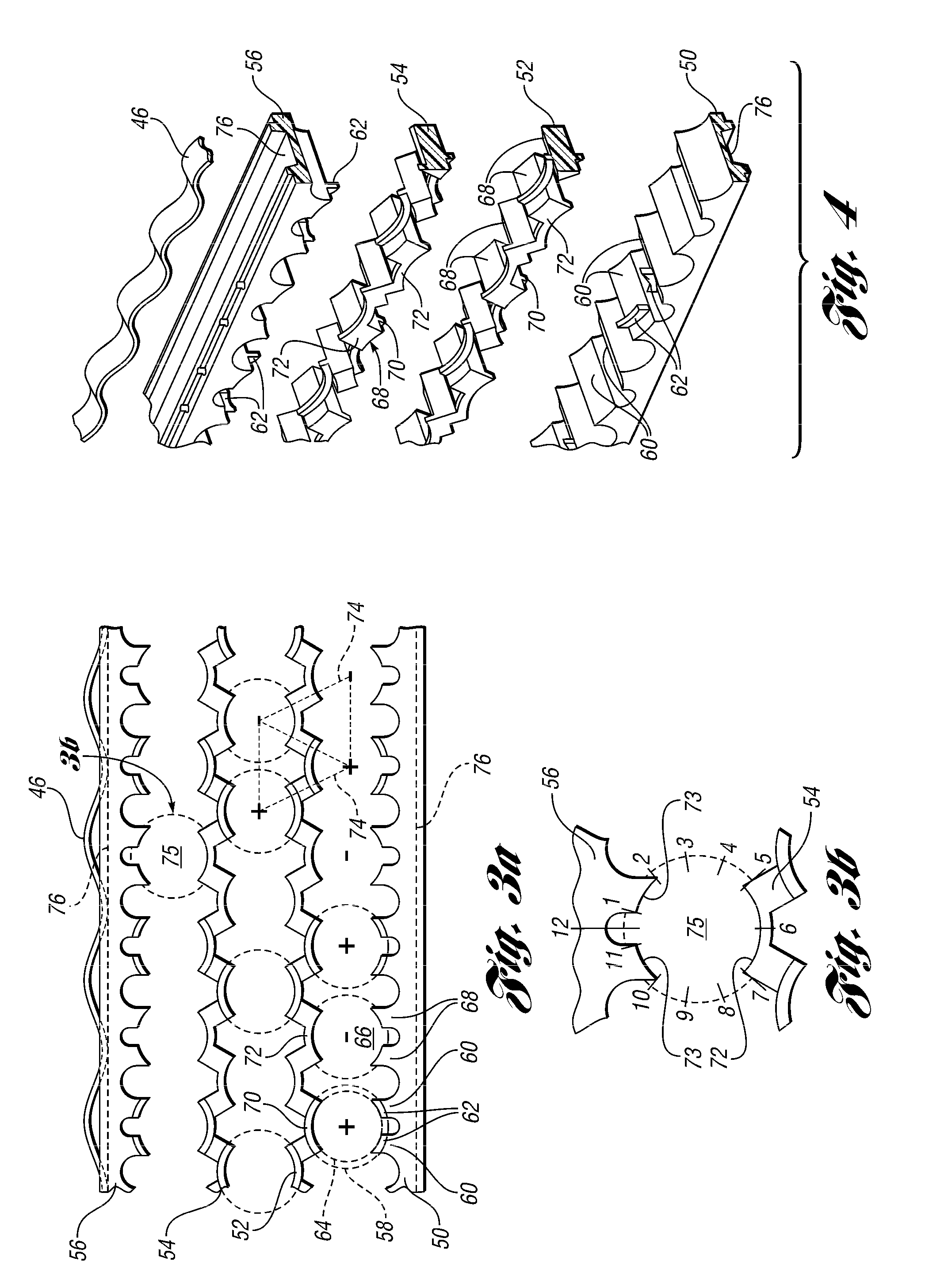
A battery having a plurality of cell pairs arranged in an array in disclosed. The cells pairs are coupled longitudinally. Sense leads are provided on the ends of cell pairs to obviate providing a sense lead proximate the junction of the cell pair.

Description

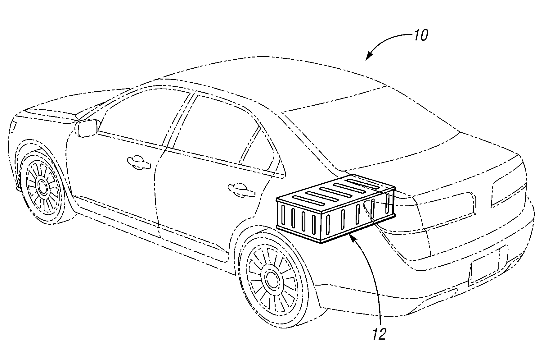
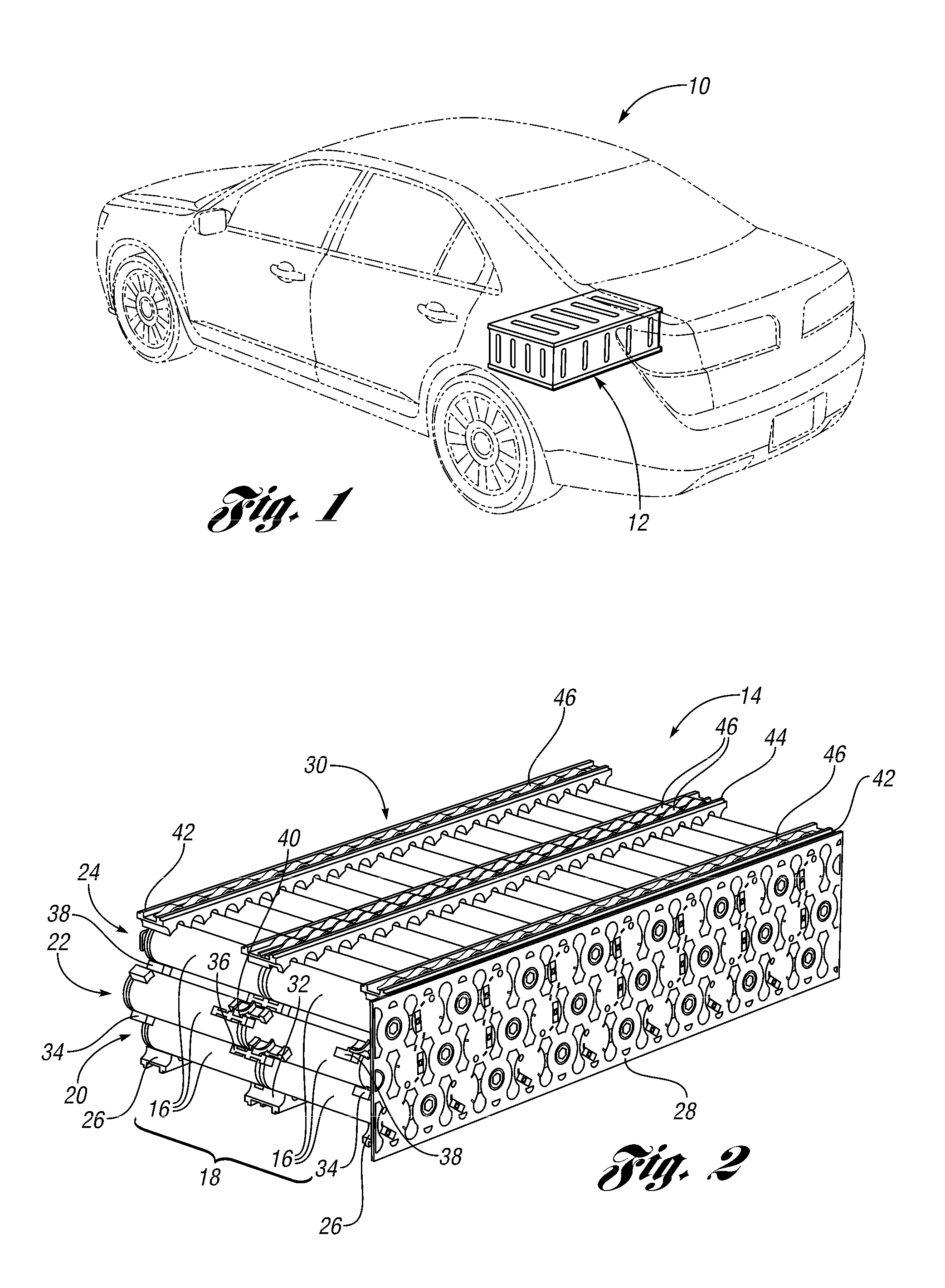
BACKGROUND1. Technical FieldThe disclosure relates to a measuring voltage in a battery comprised of a plurality of longitudinally coupled cell pairs.2. Background ArtAn electric vehicle (EV), a hybrid electric vehicle (HEV), and a fuel cell vehicle (FCV) generally include a high-voltage storage battery. In operation, the storage battery provides electric power to operate various components in the vehicle, such as an electric motor coupled to vehicle wheels. The storage battery generally includes a plurality of electrochemical cells that can store electric charge. For example, the storage battery may be a lithium-ion battery. Some issues that arise include: efficiently packaging an array of cells, effectively coupling the cells to provide the desired battery characteristics, providing sufficient cooling to ensure that the cells do not overheat, and providing sensors to all, or at least many, of the cells for measuring voltage and temperature to detect incipient cell operational probl...

Claims


Application Information

Patent Timeline
IPC IPC(8): H01M10/48H01M2/24H01M50/213H01M50/505H01M50/528H01M50/529H01M50/569
CPCG01R31/3658H01M2/1077H01M2/24H01M10/0525H01M10/48Y02T10/7077Y02T10/7011H01M2/206H01M2/22H01R11/288H01M2220/20H01M10/486G01R31/396G01R31/364Y02E60/10H01M50/529H01M50/213H01M50/505H01M50/569Y02T10/7072H01M50/528
Inventor MAGUIRE, PATRICK DANIEL
Owner FORD GLOBAL TECH LLC
Why Eureka
Try Eureka