System and method for identification of complex permittivity of transmission line dielectric

a technology of transmission line dielectric and permittivity, which is applied in the direction of dielectric property measurement, resistance/reactance/impedence, instruments, etc., can solve the problem of difficult the geometrical imperfections and large errors and the difficulty of all approaches based on gamma to solve the hyperbolic equation with measurement nois

Inactive Publication Date: 2011-07-21
SIMBERIAN
View PDF12 Cites 20 Cited by
  • Summary
  • Abstract
  • Description
  • Claims
  • Application Information

AI Technical Summary

Problems solved by technology

The major problem with all dielectric identification techniques based on Gamma extraction is high sensitivity to measurement noise and imperfections in the test structures.
The most difficult part of all approaches based on Gamma is the solution of the hyperbolic equations with the measurement noise, geometrical imperfections and large errors when the length difference between the line segments is half of wavelength.
In addition, even strip-line configurations do not provide an easy way to extract the propagation constant because of the dependency of Gamma on the conductor loss and dispersion, conductor roughness and high-frequency dispersion due to in-homogeneity of the dielectric layers adjacent to the strip in the PCB applications.
Approximate formulas used to convert Gamma into dielectric constant may lead to different types of defects—such as overestimated loss tangent due to not accounting for the conductor roughness or plating.
It means that simplified formula-based models or static and quasi-static solutions are practically useless above 3-5 GHz both for the dielectric parameters identification and for the compliance analysis.

Method used


Image

  • System and method for identification of complex permittivity of transmission line dielectric
  • System and method for identification of complex permittivity of transmission line dielectric
  • System and method for identification of complex permittivity of transmission line dielectric

Examples


Embodiment Construction

Invention Components

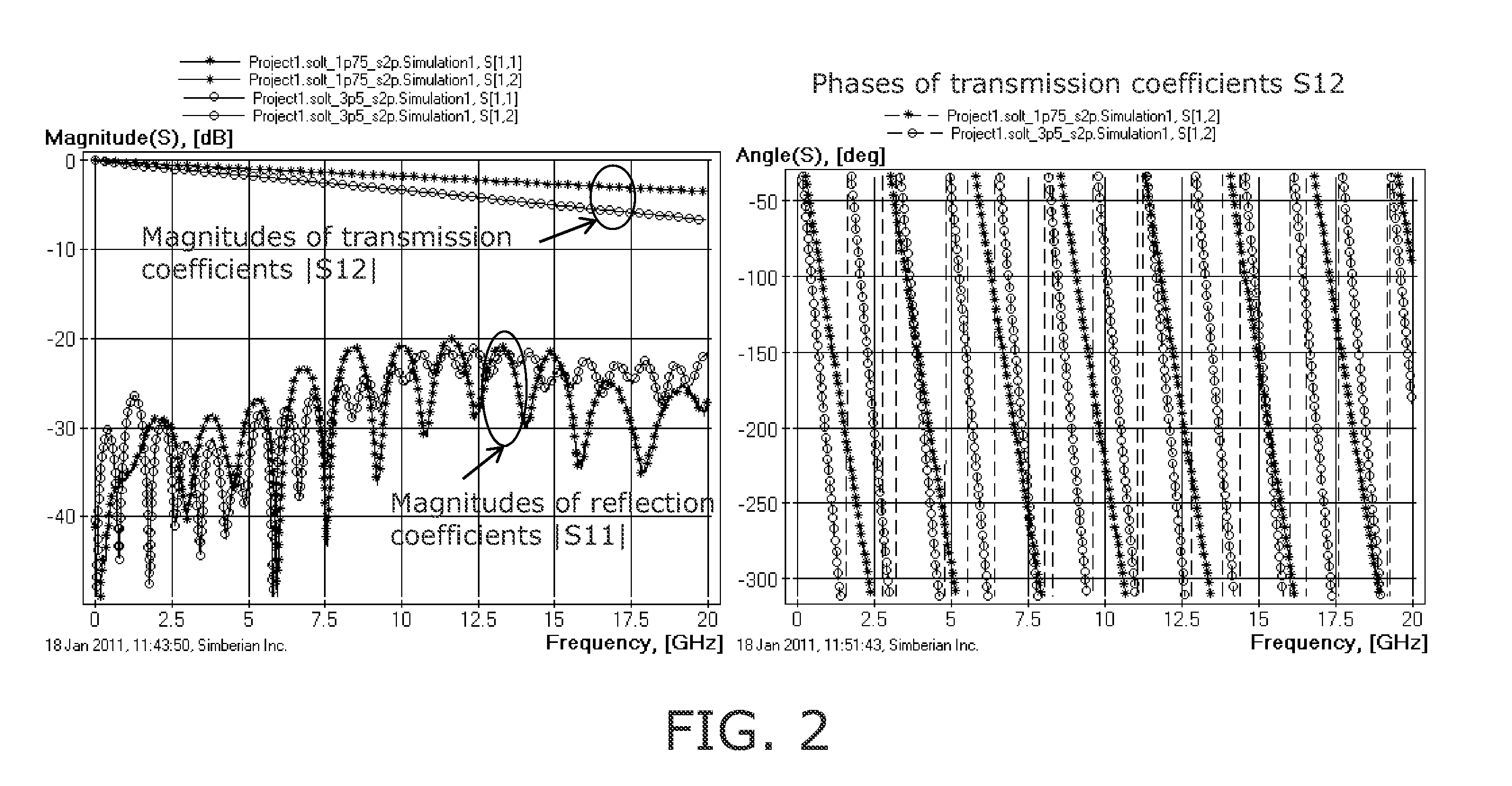
[0029]1) Network analyzer such as Vector Network Analyzer (VNA) or Time-Domain Network Analyzer—an apparatus that measures complex scattering parameters (S-parameters) of a multiport structure.

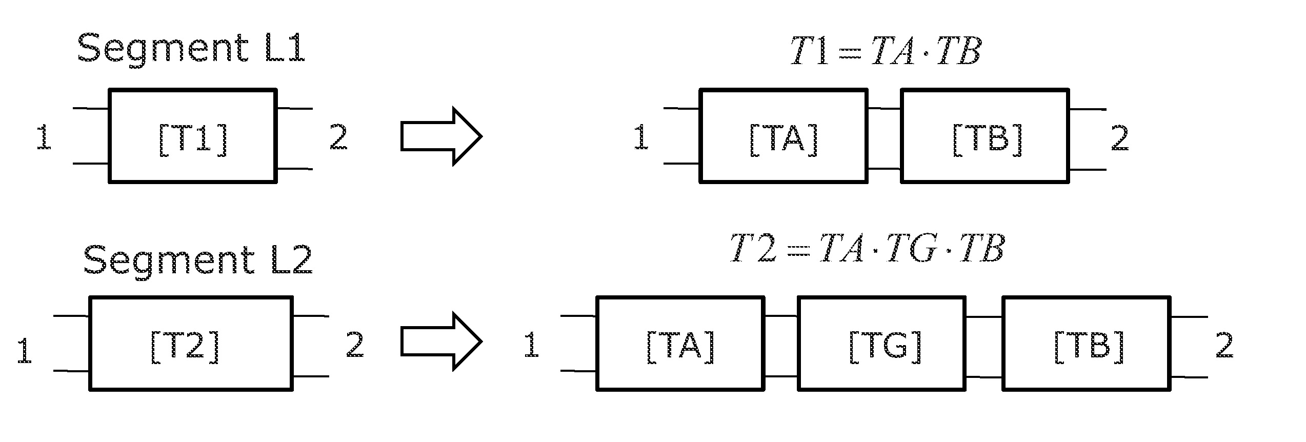
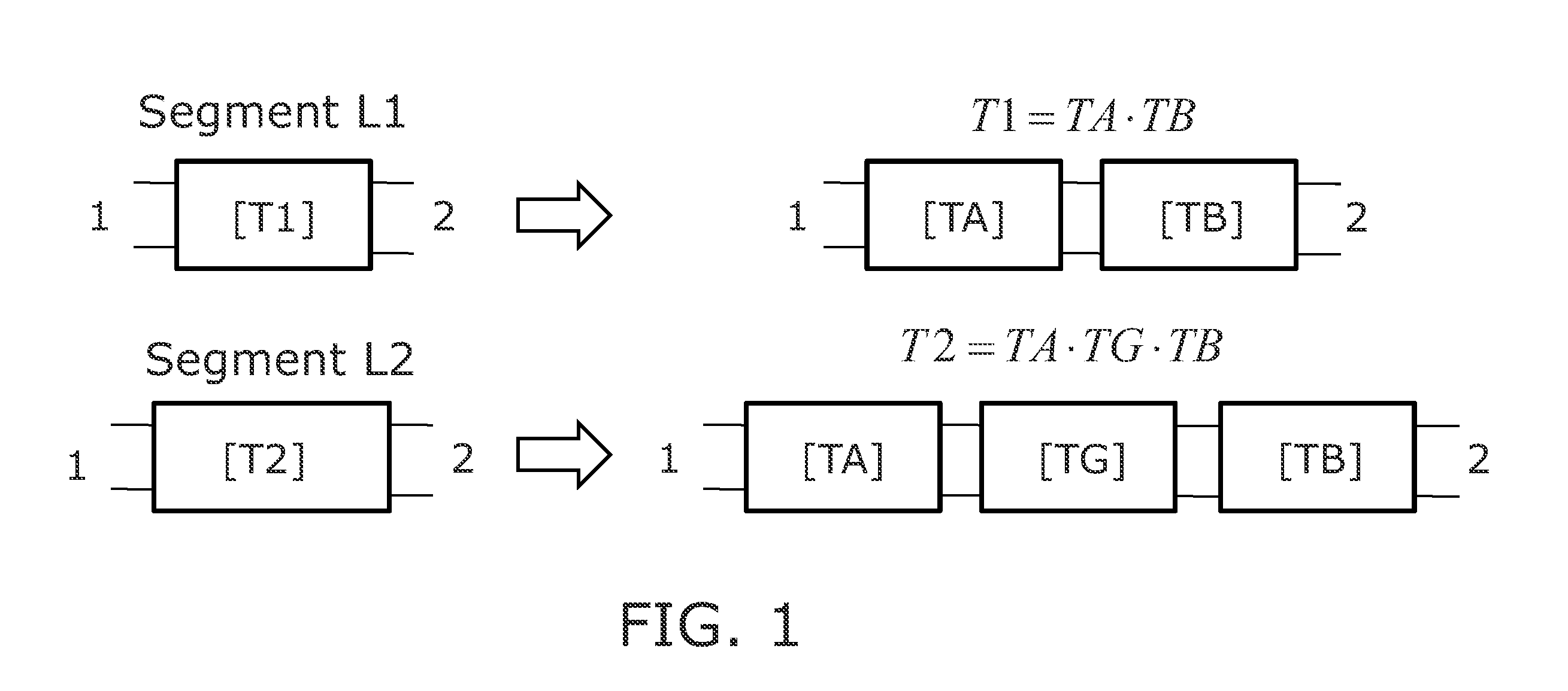
2) At least two transmission line segments with substantially identical cross-section filled with investigated dielectric. One or multi-conductor strip or microstrip line, coplanar waveguide or any other line type can be used. Two segments must have different length—one segment is shorter and another is longer. Geometry of the cross-section and conductor parameters such as bulk resistivity and roughness must be known. Both segments are equipped with either coaxial connectors or conductive probe pads to measure S-parameters over a given frequency range.

3) Procedures (first engine) of non-reflective or generalized modal S-parameters of line segment difference from two sets of S-parameters measured for two line segments.

4) Procedures (second engine) of non-reflective or genera...


PUM


Abstract

A system and method for identification of complex permittivity associated with a transmission line dielectric is proposed. A network analyzer measures scattering parameters over a specified frequency band for at least two line segments of different length and substantially identical cross-section filled with a dielectric. A first engine determines non-reflective (generalized) modal scattering parameters of the difference segment based on the measured scattering parameters of two line segments. A second engine computes generalized modal scattering parameters of the line difference segment by solving Maxwell's equations for geometry of the line cross-section with a given frequency-dependent complex permittivity dielectric model. A third engine performs optimization by changing dielectric model parameters and model type until the computed and measured generalized modal scattering parameters match. The model that produces generalized modal S-parameters closest to the measured is the final dielectric model.

Description

[0001]The current application claims a priority to the U.S. Provisional Patent application Ser. No. 61 / 296,237 filed on Jan. 19, 2010.FIELD OF INVENTION[0002]This invention relates generally to system and method for identification of complex permittivity associated with a transmission line dielectric. The system will make use of a network analyzer or equivalent instruments, two transmission line segments, and three engines used for calculations.BACKGROUND OF THE INVENTION[0003]Insulators or dielectrics are the media where signals propagate along the conductors of interconnects or transmission lines. Composite PCB and packaging dielectrics can be described with complex permittivity ∈=∈′−i·∈″ that exhibit strong dependency on frequency. Dielectric constant ∈′ and loss tangenttanδ=ɛ″ɛ′are changing substantially over the frequency band of multi-gigabit signal spectrum. Dispersive dielectric models are required from DC up to 20 GHz for 10-20 Gb / s signals, and up to 40 GHz for 20-40 Gb / s ...

Claims


Application Information

Patent Timeline
Patent Type & Authority Applications(United States)
IPC IPC(8): G06F19/00
CPCG01R27/2617G06F17/5036G06F30/367
Inventor SHLEPNEV, YURIY
Owner SIMBERIAN
Why Eureka
Try Eureka