Method for correcting measurement errors and electronic component characteristics measuring device

a technology of electronic components and measurement errors, applied in the direction of speed/acceleration/shock measurement, resistance/reactance/impedence, instruments, etc., can solve the problems of difficult adjustment, measurement errors, and inability to identify electrical errors precisely, so as to improve the yield ratio of electronic components and improve the accuracy of correction. precision, the effect of improving the yield ratio

Active Publication Date: 2011-07-21
MURATA MFG CO LTD
View PDF5 Cites 8 Cited by
  • Summary
  • Abstract
  • Description
  • Claims
  • Application Information

AI Technical Summary

Benefits of technology

[0013]To overcome the problems described above, preferred embodiments of the present invention provide a method for correcting measurement errors and an electronic component characteristics measurement device that improve correction precision by eliminating correction errors caused by leakage signal components between ports of the measurement jigs.
[0015]According to the method described above, the electrical characteristics are estimated using the equation that assumes the leakage signals between the ports. Therefore, when a relative correction is made by using a test measurement jig and a standard measurement jig in which leakage signals are present between the ports, the correction precision of the measurement errors will be improved as compared to a case in which the electrical characteristics are estimated using an equation that does not assume leakage signals between the ports.
[0022]The precision of correcting measurement errors will be improved by using a relative error correction circuit network in which connection is established between different ports at which the presence of leakage signals is assumed.
[0034]According to various preferred embodiments of the present invention, the correction precision can be improved by eliminating the correction errors caused by leakage signal components between the ports of the measurement jigs. This improves the yield ratio of the electronic components and ensures highly precise characteristics. Also, even if the leakage signal components increase as a result of a reduction in the size of electronic components, the reduction in size of the electronic components can be easily dealt with by improving the correction precision. Further, there is no need to design and manufacture the measurement jigs by paying particular consideration to the leakage signals, whereby cost reduction can be achieved.

Problems solved by technology

In such a measurement, variations in the characteristics among individual measurement jigs and variations in the characteristics among individual coaxial cables and measurement devices cause measurement errors.
However, in a measurement jig, it is not possible to identify precisely the errors of electrical characteristics between the connection terminal of the portion on which the electronic component is mounted and the coaxial connector for connecting to the coaxial cable.
Also, it is not easy to make adjustments so that the characteristics among the measurement jigs are equal or substantially equal to each other.
In particular, it is extremely difficult to adjust the measurement jigs so that the characteristics among the measurement jigs are equal or substantially equal to each other in a large bandwidth.
However, the above-described relative correction adaptor does not treat leakage signal components that are directly transmitted between the ports of measurement jigs and are not transmitted to the electronic component connected between the ports as a factor to be corrected.
For this reason, correction errors will remain due to the leakage signal components that are present in a significant amount in the measurement jigs.
Such correction errors necessitate an increase in the margin for determining good or bad products in the selection step by the amount of the correction errors, thereby causing a decrease in the yield ratio.
Moreover, according as the continued reduction in the size of electronic components, the distance between the ports will be reduced, and the leakage signal components of the measurement jigs for measuring the electronic components will be increased, whereby the correction errors will also inevitably increase.
For this reason, it will not be sufficient to merely increase the margin for determining good or bad products, leading to a possibility that the determination of good or bad products itself cannot be performed in the selection step.

Method used


Image

  • Method for correcting measurement errors and electronic component characteristics measuring device
  • Method for correcting measurement errors and electronic component characteristics measuring device
  • Method for correcting measurement errors and electronic component characteristics measuring device

Examples


Embodiment Construction

[0049]Hereinafter, preferred embodiments of the present invention will be described with reference to FIGS. 1 to 11B.

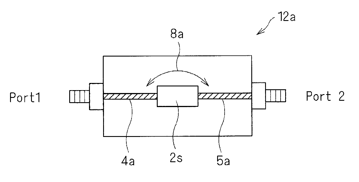
[0050]Referring to FIG. 8, electrical characteristics of an electronic component 2 (for example, a surface acoustic wave filter which is a high-frequency passive electronic component) are measured using a measuring device 10 (for example, a network analyzer) in a state in which the electronic component 2 is mounted on a measurement jig 12. Connection is established between a coaxial connector 12a of the measurement jig 12 and the measuring device 10 by a coaxial cable 14. As shown by an arrow 16, when the electronic component 2 is mounted on a mounting portion 12b of the measurement jig 12, a terminal 2a of the electronic component 2 is electrically connected to the measuring device 10. The measuring device 10 measures the electrical characteristics of the terminal 2a of the electronic component 2 by inputting a signal to a certain terminal and detecting an output sig...


PUM


Abstract

A method for correcting measurement errors and an electronic component characteristics measurement device improve correction precision by eliminating correction errors caused by leakage signal components between ports of the measurement jigs. An equation that correlates measurement values in a test measurement jig mounted state with measurement values in a standard measurement jig mounted state is determined from a result of measuring electrical characteristics of correction data obtaining samples having different electrical characteristics from each other in a state in which they are mounted on a standard measurement jig and on a test measurement jig. The equation is an equation that assumes the presence of leakage signals that are directly transmitted between at least two ports of at least one of the standard measurement jig and the test measurement jig. By using the equation determined by measuring the electrical characteristics on an arbitrary electronic component in a state in which it is mounted on the test measurement jig, the electrical characteristics that would be obtained if measured on the electronic component in a state in which it is mounted on the standard measurement jig are calculated.

Description

BACKGROUND OF THE INVENTION[0001]1. Field of the Invention[0002]The present invention relates to a method for correcting measurement errors and an electronic component characteristics measuring device. More particularly, the present invention relates to a method for correcting measurement errors and an electronic component characteristics measuring device that calculate an estimated value of electrical characteristics that would be obtained if measured in a state in which an electronic component is mounted on a standard measurement jig from a result of measuring the electrical characteristics in a state in which the electric component is mounted on a test measurement jig.[0003]2. Description of the Related Art[0004]Conventionally, an electronic component that does not have a coaxial connector, such as a surface-mounting type electronic component, may be mounted on a measurement jig having a coaxial connector, and the measurement jig may be connected to a measuring device via a coaxi...

Claims


Application Information

Patent Timeline
Patent Type & Authority Applications(United States)
IPC IPC(8): G06F19/00
CPCG01R35/005G01R27/28
Inventor MORI, TAICHI
Owner MURATA MFG CO LTD
Why Eureka
Try Eureka