Multi-purpose mobile modular structure

a mobile, modular technology, applied in the direction of structural elements, building components, load-supporting elements, etc., can solve the problems of difficult transportation to the site of use, limited configurations obtainable using shipping containers, and similar problems in assembly processes, so as to achieve the effect of drastically reducing the difficulty of manufacturing, handling, storage and transportation of modular structures

Inactive Publication Date: 2011-07-28
YEN CHIH CHENG
View PDF23 Cites 42 Cited by
  • Summary
  • Abstract
  • Description
  • Claims
  • Application Information

AI Technical Summary

Benefits of technology

[0014]The present invention consists of a structure using a system of beams and joints to create a modular structure using a basic “C” frame unit that is expandable and reconfigurable. The use of a system which can be assembled only when necessary, instead of a partially or fully completed structure, me

Problems solved by technology

Transportation to the site of use also poses challenges because the partially completed units will require vehicles that are built to accommodate the weight and size of the structures.
Similar problems also apply to the assembly process.
Heavy lifting equipment will be necessary to handle the partially completed structures during the assembly process because of the weight and size of some of these units or modules.
The problems that are associated with pre-fab buildings also apply to containers.
The size and weight of shipping containers necessitate the need for heavy equipment during the manufacturing, transportation and assembly process.
The configurations ob

Method used


Image

  • Multi-purpose mobile modular structure
  • Multi-purpose mobile modular structure
  • Multi-purpose mobile modular structure

Examples


embodiment 2

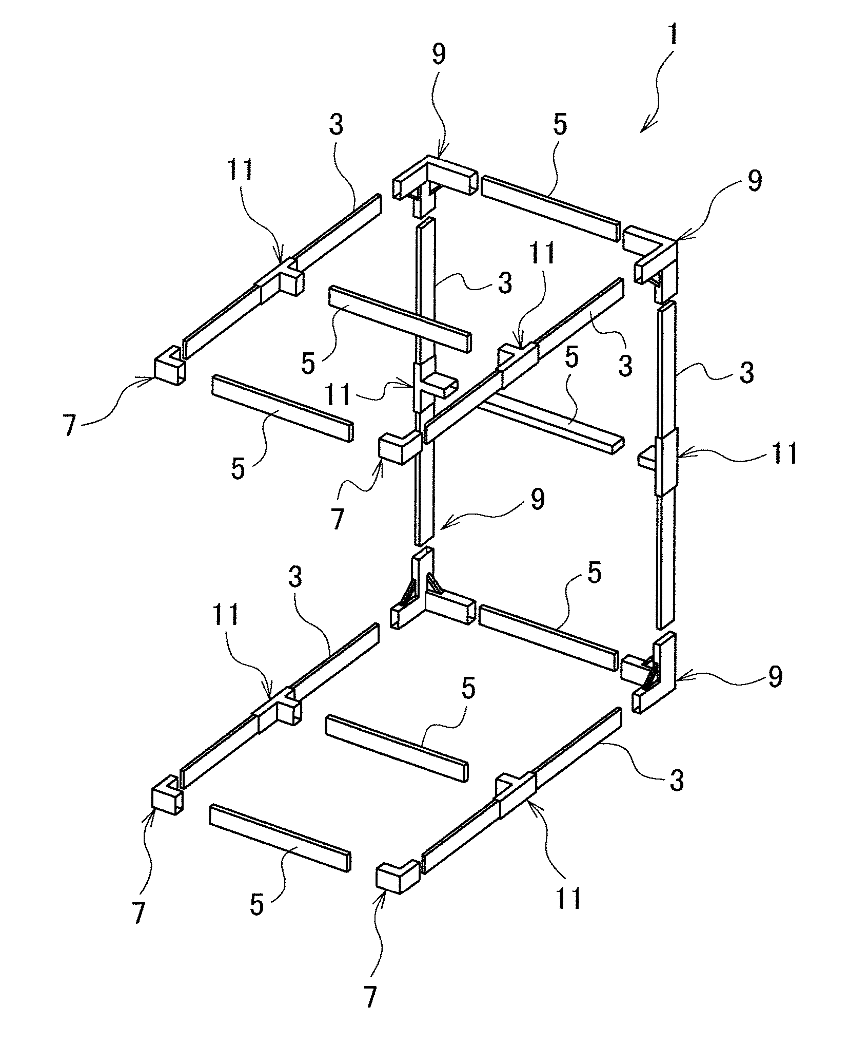
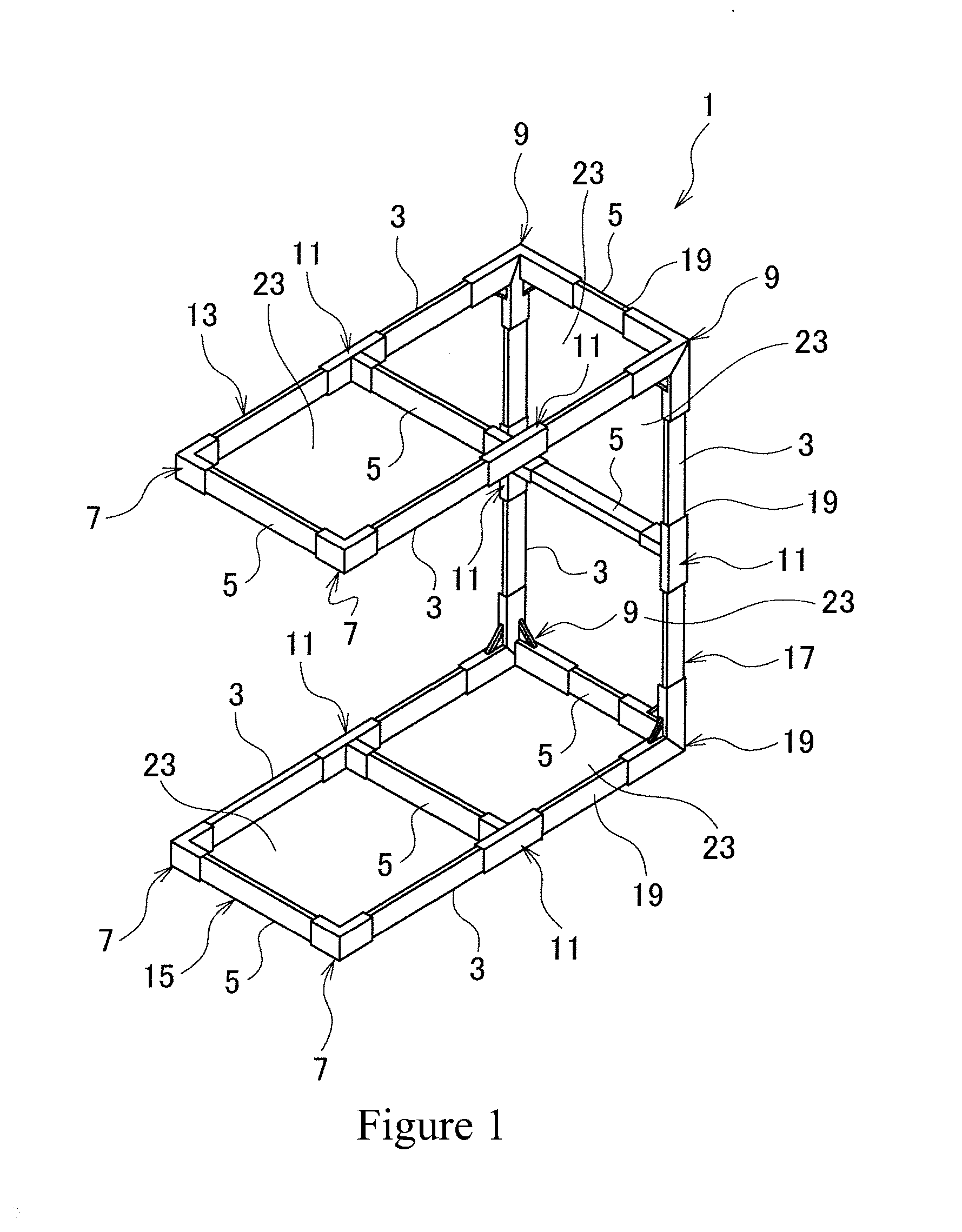
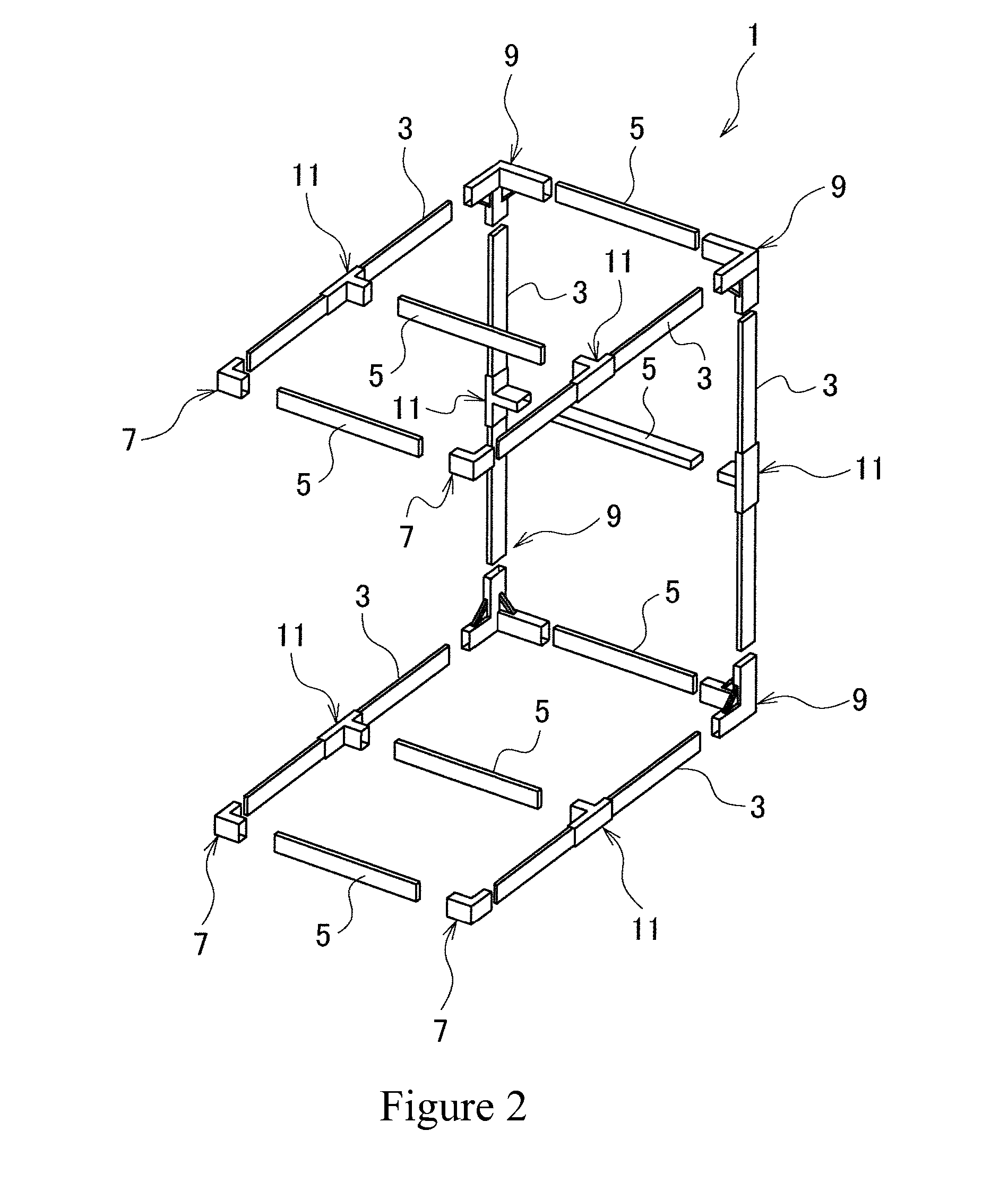
[0141]FIG. 13 is the perspective view of the embodiment 2 of the present invention which relates to the frame assembly of the modular structure, FIG. 14 is the cross-sectional view of FIG. 13, FIG. 15 shows the joints being used for the frame assembly in FIG. 13, FIG. 16 shows the center joint being used in the frame assembly in FIG. 13. Because the basic structure of this embodiment is the same as that of embodiment 1, the structural components are numbered similarly and also added with an “A” and detailed explanation is omitted.

[0142]The frame assembly 1A for this embodiment is similar to FIGS. 13 and 14, end joint 135 and the center joint 137 are used for expansion of the structure. In this embodiment, the outer frame sections 19A of the upper section 13A, the lower section 15A and the side section 17A form four cavities 23A.

[0143]The said end joint 135, as shown in FIGS. 13 to 15, is affixed between two end joints 9 on either side and together with said end joints 9 form the “C”...

modified embodiment

[0150]In this embodiment, as shown in FIG. 17, by using the end joint 135 and the center joint 137 appropriately, the frame assembly 1B can be further expanded. In this modified embodiment, the outer frame section 19A of the upper section 13A and the lower section 15A and the side section 17A form nine cavities 23B.

[0151]Accordingly, in the frame assembly 1B, the use of the end joint 135 and the center joint 137 to further expand the structure also allows it to distribute the load even further.

embodiment 3

[0152]FIGS. 18 to 27 show the joints involved in embodiment 3 of the current invention. In this embodiment, because of the similarity to embodiments 1 and 2, the numbering of the respective component will be the same with the substitution of “C” for “A” and detailed descriptions will be omitted.

[0153]In this embodiment, as shown in FIGS. 18 to 27, joints 139, 140, 149, 157, 161, 165, 167, 171, 175, 179 can be used to further augment the frame assembly and also the form of the frame assembly in added flexibility.

[0154]The joint 139 in FIG. 18 is an end joint that is essentially the end joint 9 in embodiment 1 added with an end support sleeve 141 in the rear face.

[0155]That is, joint 139 is formed by the end support sleeve 141 on the vertical wall 55 on the rear face of end support joint 73C. With this, joint 139 forms a “T” shape body when viewed from the top and also from the side.

[0156]The said end support sleeve 141 is longer than the end support joint 71C. End support sleeve 141 ...


PUM


Abstract

A modular building system is disclosed. The modular building includes a plurality of pre-fabricated joints having open-ended hollow arms extending orthoganally along at least two directional axes, as defined by a 3-dimensional rectangular coordinate system. The system further includes a plurality of pre-fabricated beams detachably insertable into the open-ends of the hollow arms of the joints and connectors removeably securing the beams in the hollow arms of the joints. The joints and beams are assembled to build a variety of modular grid-frame structures in accordance with pre-determined assembly plans.

Description

FIELD OF THE INVENTION[0001]The invention relates to a mobile modular building system that can be rapidly deployed to create usable space for different purposes. The invention also relates to all joints and connectors that are integral parts of the invention.BACKGROUND OF THE INVENTION[0002]Modular structures have been used in various applications. Modular structures are usually designed to combine standard components in different combinations to create varied configurations.[0003]An example of modular structures is pre-fabricated or “pre-fab” housing. Pre-fabricated housing are usually manufactured in a remote location and then transported to the place of use for assembly. These homes are usually manufactured in a large facility into partially completed structures before being transported and assembled.[0004]This method of construction necessitates the use of a large facility during the manufacturing process because of the need to handle the large assemblies. Transportation to the ...

Claims


Application Information

Patent Timeline
IPC IPC(8): E04C3/04E04B1/38
CPCE04C2003/043E04C2003/0465E04B2001/2421E04B2001/0076E04B2001/2406E04B1/34326
Inventor YEN, CHIH-CHENG
Owner YEN CHIH CHENG
Why Eureka
Try Eureka