Electronic side view display system

a display system and side view technology, applied in closed circuit television systems, television systems, color television details, etc., can solve the problems of limited field of view, minors may not be optimally adjusted for backing up, and provide the driver with a comprehensive view, so as to improve fuel economy, enhance information available, and improve safety and convenience.

Inactive Publication Date: 2011-07-28
DELPHI TECH INC
View PDF15 Cites 101 Cited by
  • Summary
  • Abstract
  • Description
  • Claims
  • Application Information

AI Technical Summary

Benefits of technology

[0012]The present invention relates to an electronic replacement for driver and passenger side view mirror systems, and provides a set of unique features which enable new possibilities for improved fuel economy, safety and convenience. The present invention relies upon electronic imaging cameras and electronic active matrix displays (e.g. LCD, OLED, etc.) for reproducing the image. Although camera based viewing systems have been proposed previously, the present invention is embodied in specific, unique features which can be incorporated to enhance the information available to the vehicle driver.

Problems solved by technology

However, conventional side view mirrors have a limited field of view and do not provide the driver with a comprehensive view of the area, so objects in portions of the area alongside and behind a vehicle may not be seen by the driver.
For example, if the minor position is adjusted by the driver to be optimum for traveling in a forward direction where the driver is observing an adjacent traffic lane rearward the vehicle, then the minor may not be optimally adjusted for backing up where the driver needs to see the area near the rear wheel and rear bumper.
However, this provision has an undesirable time response delay due to the mechanical motion, and adds undesirable cost and complexity to the mirror assembly.
As with side view mirrors, mechanically changing the aimed direction of a camera using a mechanical position control system has the same undesirable cost, complexity, and time response delay problems as the motorized mirrors.
Incomplete visibility to each side of the vehicle, causing blind spots which can lead to lane-change-type accidents; and
Susceptibility of damage to the mirrors or to adjacent vehicles due to the protrusion of the minor outside the plane of the vehicle.

Method used


Image

  • Electronic side view display system
  • Electronic side view display system
  • Electronic side view display system

Examples


Embodiment Construction

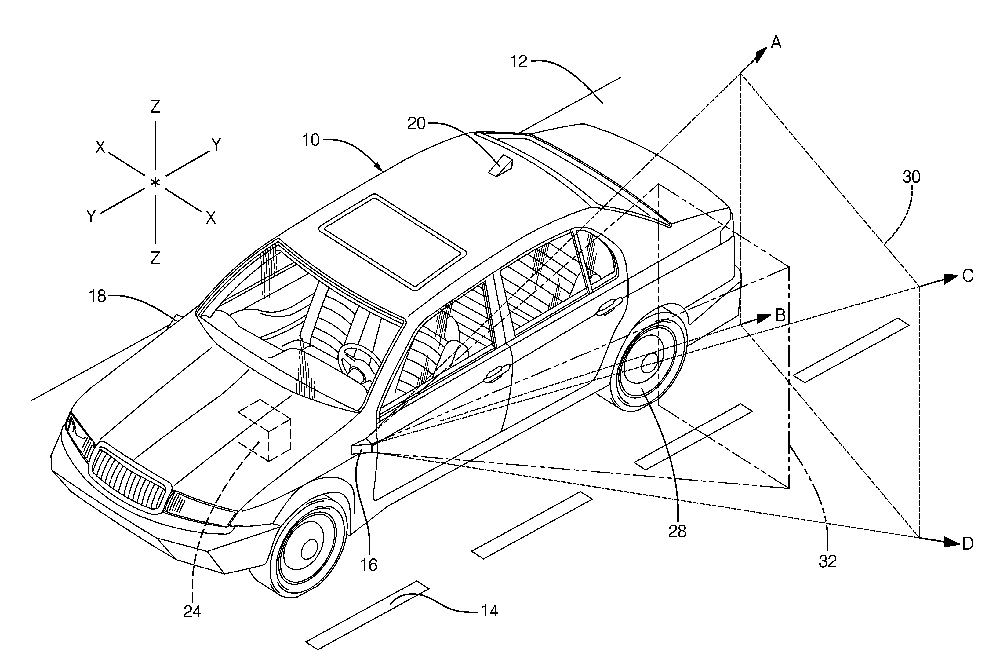
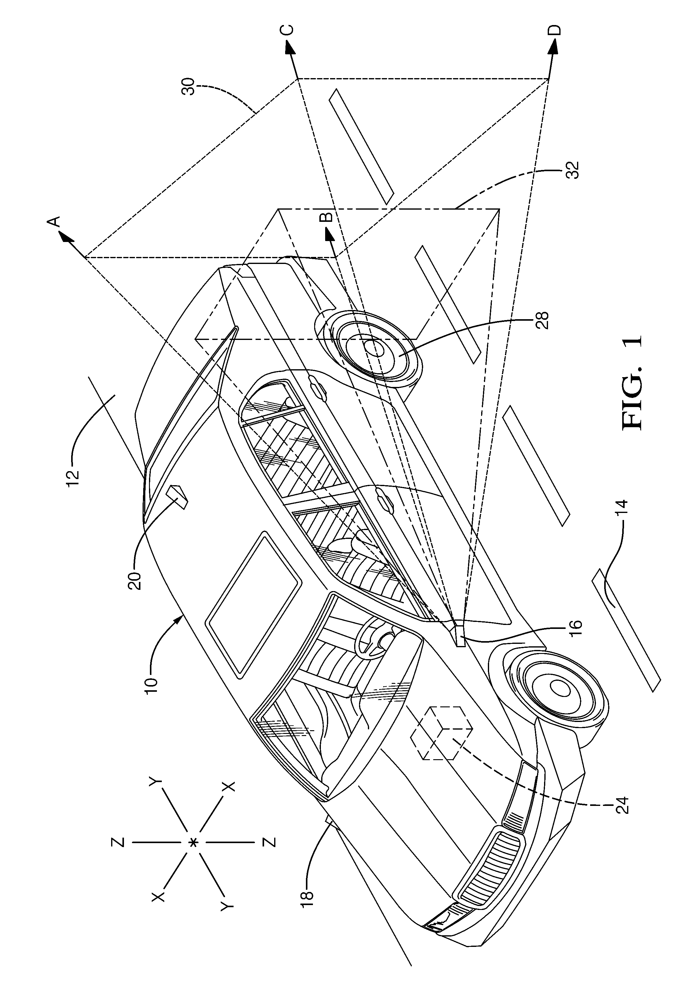
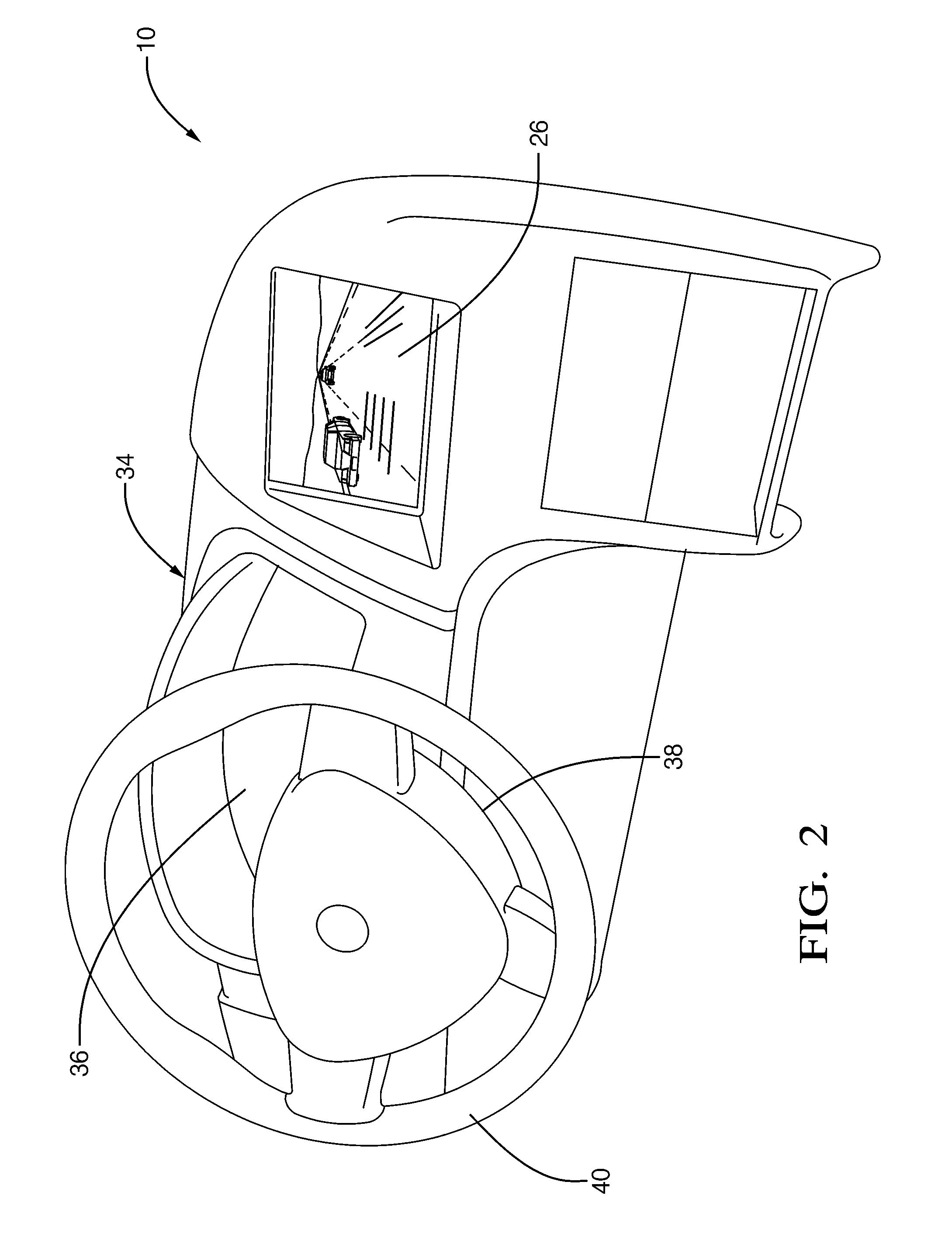
[0023]The invention described herein relates to an electronic replacement for driver and passenger side view mirror systems, specifically, a set of unique features which enable new possibilities for improved fuel economy, safety and convenience. The present invention relies upon electronic imaging cameras and electronic active matrix displays (e.g. LCD, OLED, etc.) for reproducing the image. Although camera based viewing systems have been proposed previously, the present invention is embodied in specific, unique features which can be incorporated to enhance the information available to the vehicle driver.

[0024]Through the use of an additional video processing component of the system (e.g. field-programmable gate array, graphic processing unit, or equivalent) to accept the raw camera input and process it before sending to the display element, numerous performance enhancements are possible. Specifically, features such as the following are possible:

[0025]Electronically-Adjustable Field...


PUM


Abstract

An apparatus provides an electronic replacement for driver and passenger side view minor systems. Specifically, a set of unique features provide enhanced fuel economy, safety and convenience. The invention relies upon electronic imaging cameras and electronic active matrix displays (e.g. LCD, OLED, etc.) for reproducing the image, with the addition of reality enhancing features.

Description

TECHNICAL FIELD[0001]The present invention relates to apparatus enhancing a driver's visibility or field of view externally of a ground vehicle, such as an automobile, motorcycle, truck or the like.BACKGROUND OF THE INVENTION[0002]It is known to provide side view mirrors on vehicles to assist a driver with viewing an area alongside and behind a vehicle. Minors are useful for assisting the driver in seeing obstacles prior to changing lanes or backing up, where the obstacles might otherwise collide with the vehicle. However, conventional side view mirrors have a limited field of view and do not provide the driver with a comprehensive view of the area, so objects in portions of the area alongside and behind a vehicle may not be seen by the driver. These portions where unseen objects may reside are not seen because the conventional side view mirrors have fixed positions after being adjusted by the driver. For example, if the minor position is adjusted by the driver to be optimum for tra...

Claims


Application Information

Patent Timeline
Patent Type & Authority Applications(United States)
IPC IPC(8): H04N7/18
CPCB60R1/00B60R2300/303B60R2300/8046B60R2300/307B60R2300/605B60R2300/304
Inventor TIEMAN, CRAIG A.MILLER, MICHAEL E.WILOCH, FRANK BRUCE
Owner DELPHI TECH INC
Why Eureka
Try Eureka