Method for controlling HARQ operation in dynamic radio resource allocation
- Summary
- Abstract
- Description
- Claims
- Application Information
AI Technical Summary
Benefits of technology
Problems solved by technology
Method used
Image

Examples
first embodiment
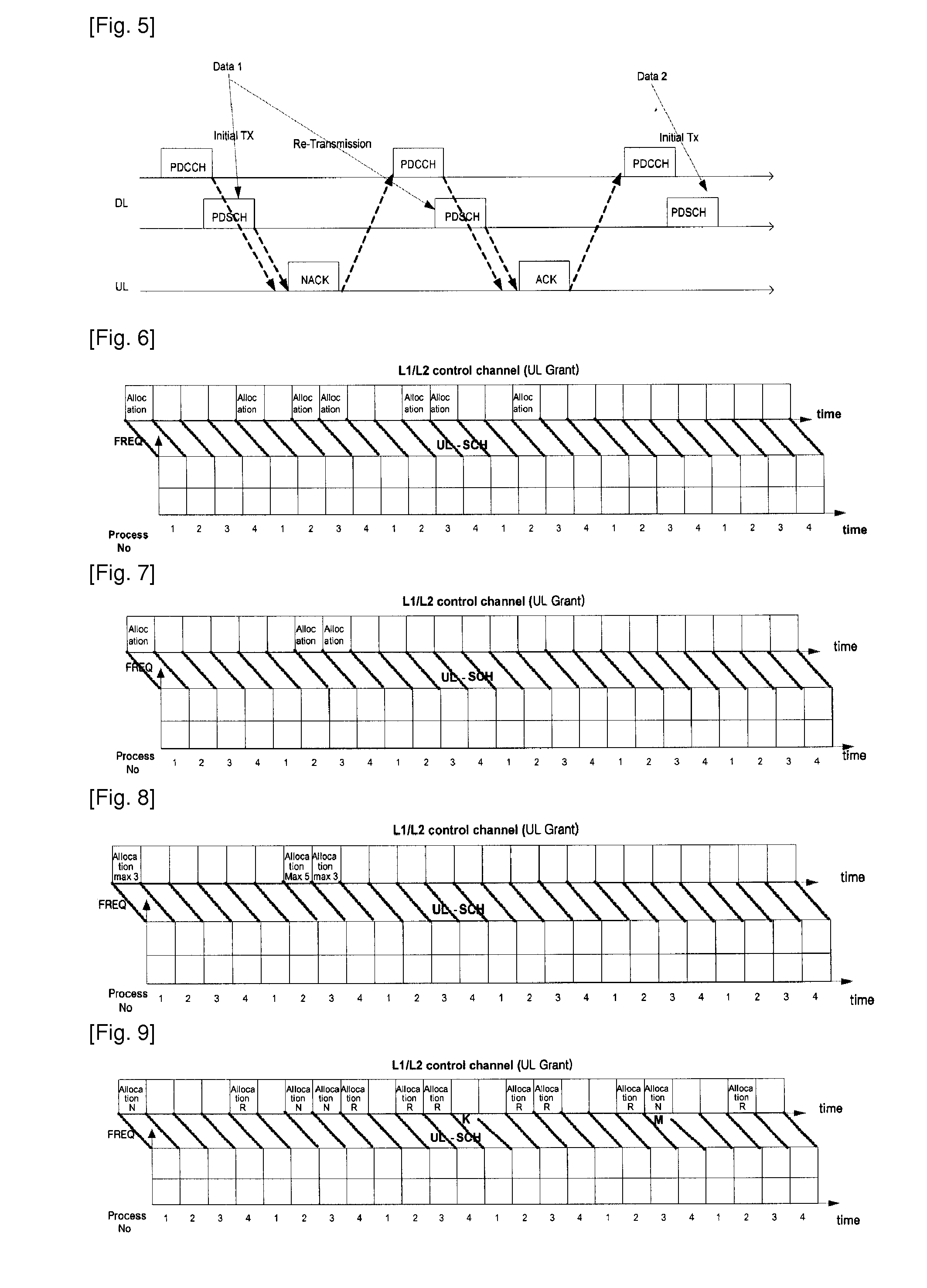
[0035]FIG. 8 is a radio resource allocation in accordance with the present invention. As shown in FIG. 8, when an uplink radio resource is allocated via a L1 / L2 control channel (i.e., Physical Downlink Control Channel (PDCCH)), a radio resource allocation message indicates a maximum number of retransmission to a UE. For example, in FIG. 8, the first radio resource allocation message indicates that the maximum number of retransmission is 3, and the second radio resource allocation message indicates that the maximum number of retransmission is 5. Therefore, the UE can retransmit first data maximum 3 times, and second data maximum 5 times. That is, when the UE receives the information related to the maximum number of retransmission through the radio resource allocation message, the retransmission is not performed more than the number of times indicated. That is, in case of a certain radio resource being allocated, if the UE exceeds the maximum number of retransmission for data which is...
second embodiment
[0036]Also, in order to dynamically control the maximum number of retransmission, the UE may be allowed to perform the retransmission until a certain event is generated. That is, upon transmitting a certain data block, the UE can continue to retransmit the data being transmitted, if the UE has not been allocated a radio resource required for the retransmission of the data block or until it receives an indication as to an initial transmission of new data. In other words, if the UE has not been allocated a radio resource required for the retransmission of a data block or receives the indication as to the initial transmission of new data, it is assumed that the UE has reached the limit of maximum number of retransmission. FIG. 9 is a radio resource allocation in accordance with the present invention. In FIG. 9, “Allocation N” denotes an initial transmission of new data, and “Allocation R” denotes a retransmission of certain data. As shown in FIG. 9, an initial radio resource allocation...
third embodiment
[0037]The present invention aims to reduce the number of transmission of the radio resource allocation message. To this end, the present invention proposes an allocation of plural processes to one radio resource allocation message. FIG. 10 is a third embodiment for a radio resource allocation according to the present invention. As shown in FIG. 10, one radio resource allocation message is applied to every process (e.g., processes 1 to 4) set for a UE. Thus, upon receiving the radio resource allocation message, the UE operates with considering as being able to use a radio resource indicated in the radio resource allocation message at every process set therefor.
[0038]As another method, process information may be included in the radio resource allocation message to thusly allow a radio resource to be selectively allocated. That is, one radio resource allocation message may include information related to specific process to which such message should be applied. Accordingly, after receiv...
PUM
 Abstract
Description
Claims
Application Information
 - Generate Ideas
- Intellectual Property
- Life Sciences
- Materials
- Tech Scout
- Unparalleled Data Quality
- Higher Quality Content
- 60% Fewer Hallucinations
Browse by: Latest US Patents, China's latest patents, Technical Efficacy Thesaurus, Application Domain, Technology Topic, Popular Technical Reports.
© 2025 PatSnap. All rights reserved.Legal|Privacy policy|Modern Slavery Act Transparency Statement|Sitemap|About US| Contact US: help@patsnap.com