Portable biological signal measurement / transmission system

a biological signal and transmission system technology, applied in the field of portable biological signal measurement/transmission system, can solve the problems of high cost and bulky patient monitoring devices, and the efficiency of apparatus management and operation, and achieve the effects of low cost, high versatility, and reduced burden of signal processing in the body uni

Active Publication Date: 2011-07-28
NIHON KOHDEN CORP
View PDF25 Cites 9 Cited by
  • Summary
  • Abstract
  • Description
  • Claims
  • Application Information

AI Technical Summary

Benefits of technology

[0019]It is therefore an object of the invention to provide a biological signal measurement / transmission system, which is economical and portable and in which a biological signal processing unit including a signal processing portion that performs processing (for example, signal amplification, AD conversion, and filtering) on measurement data such as ECG, SpO2, and NIBP data, is configured so as to be separable from a body unit, whereby the burden of signal processing in the body unit is reduced so that a small data processing terminal or the like having a high versatility can be employed as the body unit, and further in which a signal processing unit corresponding to a single or plurality of sensor devices can be selectively connected to the body unit depending on the use required by the user, whereby it is possible to realize a less wasteful system which corresponds to the use.

Problems solved by technology

This limitation causes the following disadvantages; the process burden of the CPU mounted on the patient monitoring device is large, a dedicated device is required for various combinations of parameters, and the patient monitoring device is expensive and bulky so that the patient cannot move around while carrying the patient monitoring device.
Thereby, it causes a problem in efficiency of apparatus management and operation.

Method used


Image

  • Portable biological signal measurement / transmission system
  • Portable biological signal measurement / transmission system
  • Portable biological signal measurement / transmission system

Examples


first embodiment

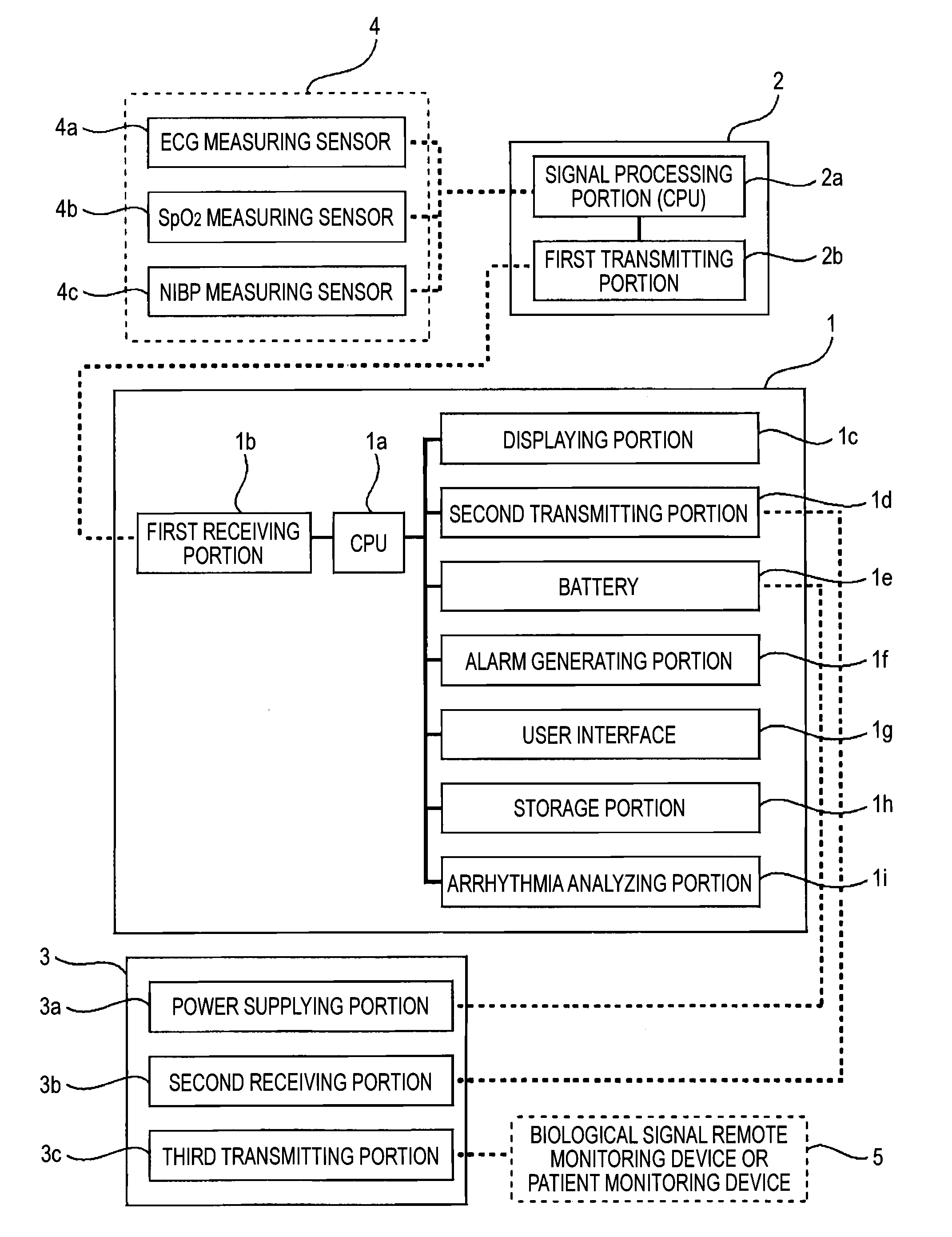
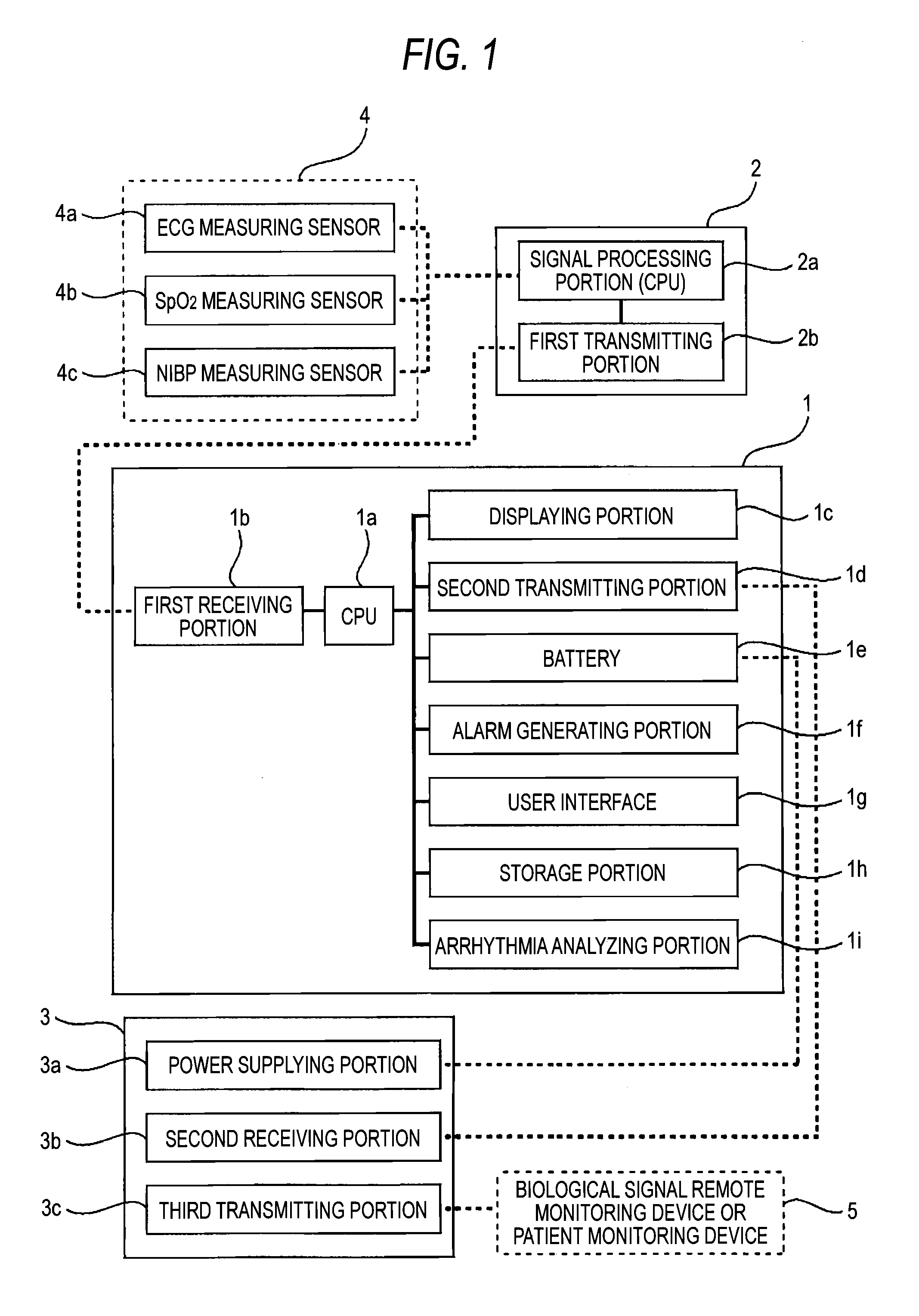
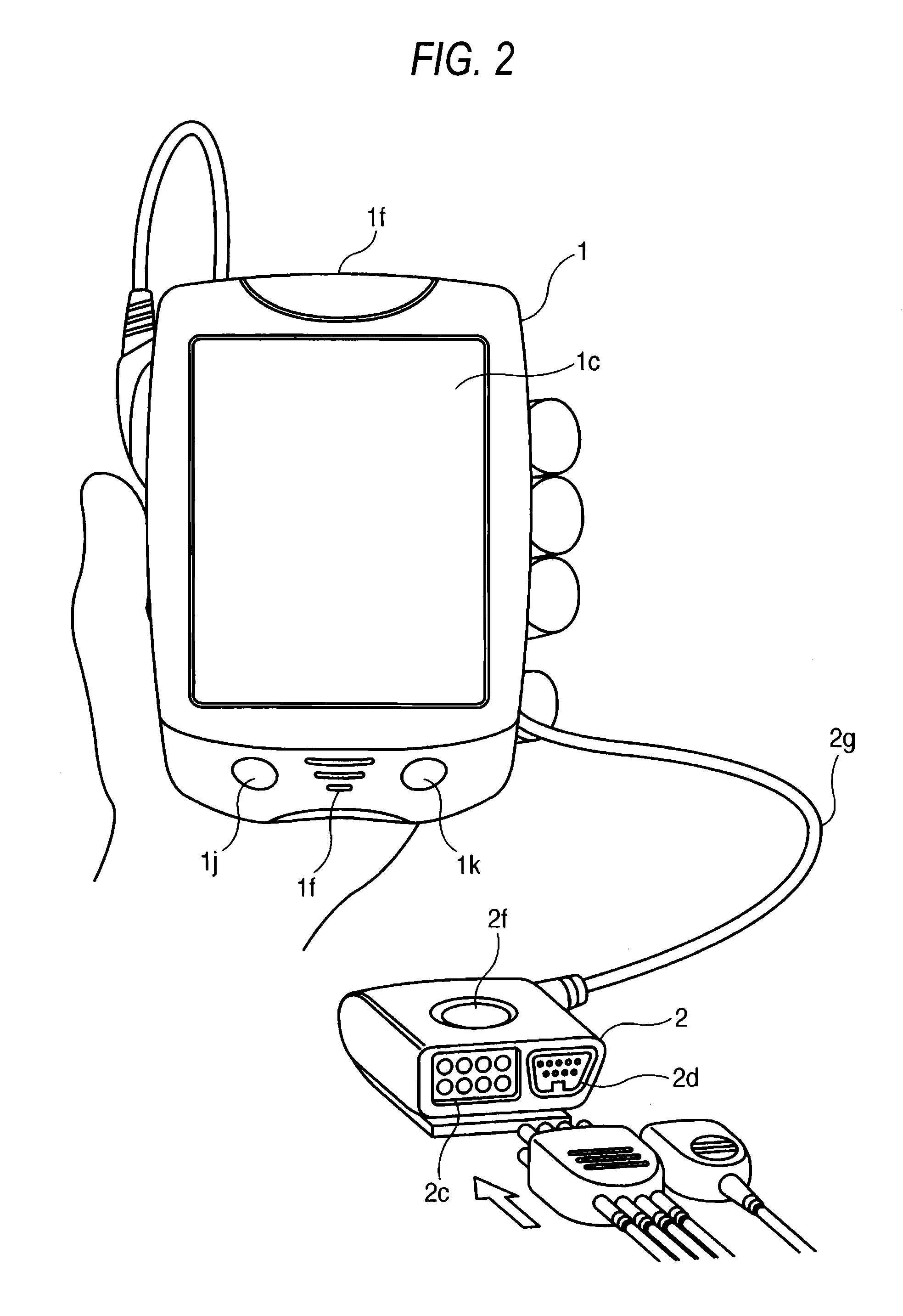
[0051]Next, the components of the portable biological signal measurement / transmission system of the invention will be described with reference to FIGS. 2 to 10. FIG. 2 is a perspective view showing in detail the body unit 1 and the biological signal processing unit 2 in the invention. In FIG. 2, 1 denotes the body unit, and 1c denotes the displaying portion which uses a color LED, and which is preferably configured as a touch panel. The reference numeral 1f in the upper side denotes an alarm indicator which is configured by an LCD, and which emits color light that is different depending on the kind of the alarm, and 1f in the lower side denotes an alarm speaker which notifies a sound alarm that is different depending on the kind of the alarm. The reference numeral 1j denotes a record key, and 1k denotes an alarm cancel key.

[0052]In FIG. 2, 2 denotes the biological signal processing unit, 2f denotes a nurse call key (nurse call switch), 2c denotes a connector for connection with the ...

second embodiment

[0058]FIG. 6 is a perspective view showing in detail a body unit and a biological signal processing unit in the invention. In FIG. 6, 1 denotes the body unit, and 1c denotes a displaying portion which uses a color LED, and which is preferably configured as a touch panel. The reference numeral 1f in the upper side denotes an alarm indicator which is configured by an LCD, and which emits color light that is different depending on the kind of the alarm, and 1f in the lower side denotes an alarm speaker which notifies a sound alarm that is different depending on the kind of the alarm. The reference numeral 1j denotes a record key, and 1k denotes an alarm cancel key.

[0059]In FIG. 6, 2 denotes the biological signal processing unit, 2f denotes a nurse call key (nurse call switch), 2c denotes a connector for connection with the ECG measuring sensor, 2d denotes a connector for connection with the SpO2 measuring sensor, and 2g denotes a connection cable for connection with the body unit 1. In...


PUM


Abstract

A portable biological signal measurement/transmission system includes: a body unit; and at least one biological signal processing unit detachably connected to the body unit, and including a signal processor which processes a biological signal, the biological signal processing unit including a first transmitter which transmits the biological signal to the body unit when the biological signal processing unit is connected to the body unit.

Description

BACKGROUND OF THE INVENTION[0001]The present invention relates to a portable biological signal measurement / transmission system which includes at least one of a plurality of sensors for measuring a plurality of biological signals such as ECG, SpO2, and NIBP and which transmits biological signal information measured by the sensor to a monitoring device.[0002]JP-T-2008-526443 discloses a related-art patient monitoring device which measures biological signals. The related-art patient monitoring device is shown in FIGS. 13 to 16. Referring to FIG. 13, the patient monitoring device 20 is defined by a housing 24 that receives input from a plurality of sensors, each forming part of physiologic sensor assemblies 28, 32 and 36, in this instance ECG, SpO2 and NIBP (non-invasive blood pressure) assemblies. The housing 24 includes a display 88 for vital sign numerics, waveforms and other patient data, as well as a user interface 92, shown in FIG. 14, that permits operation of the monitoring devi...

Claims


Application Information

Patent Timeline
Patent Type & Authority Applications(United States)
IPC IPC(8): A61B5/00A61B5/01
CPCA61B5/0002A61B5/6838A61B5/747A61B5/7235A61B5/7203G16H80/00
Inventor OGINO, HIROKAZUARIMITSU, TAKAYA
Owner NIHON KOHDEN CORP
Why Eureka
Try Eureka